I was stripping the transistors out of a Ptew Ptew PeaveyCS800 1989 series, that I was binning because I was totally frustrated and couldn't get enough info on how to get it working again when I came across a transistors pin that wasn't quite long enough to have enough contact,so it was Aha! and A quick replacement of the transistor and it had the correct power again.The trouble is it still keeps losing power every now and then? Ive checked the transformer when it was playing up (if it is the tranny) and it had 20vDC on the rails instead of 74vDC. I measured the primary side with a DMM set to ohms, With power off and measuring black active wire to grey center tap 1.5 ohms,black to white 1.6 ohms,white to gray center tap 0.4 ohms. secondary, red to red 0.6 ohms,red to chassis 0.6 ohms. Brown to brown 0.6 ohms,brown to chassis 0.4 ohms. With power on it was normal with 57vAC on both red secondary's and 18vAC on the brown secondary's.Could this intermittent power problem be caused by the big filter caps? they measure OK with a capacitance meter but I don't have an ESR meter to check the resistance.The power board sits on top of them and they would cop a lot of heat and they are only 85c rated.Does anyone know what I could do to fix this (to me) Heath Robinson contraption.LOL
Some guides
Hi ,
Just a suggestion
1. The power supply can tested with any bulb & a amp meter , please disconnect the amp boards , power the bulb with a the transformer supply after the bridge & smooth caps , if the power supply chokes it is a power supply issue
else it may be
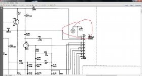
2. Protection , the ddt built around a few 4558 ic s sometimes chokes the output
3. finally there is a triac mounted on the heat sink in some of old peavey amps (as a protection) the triac chokes the supply to the output devices or so , ive forgotten have been off repairing & electronics for quite some time now .
Oh , best of luck with the contraption ...
Suranjan
Hi ,
Just a suggestion
1. The power supply can tested with any bulb & a amp meter , please disconnect the amp boards , power the bulb with a the transformer supply after the bridge & smooth caps , if the power supply chokes it is a power supply issue
else it may be
2. Protection , the ddt built around a few 4558 ic s sometimes chokes the output
3. finally there is a triac mounted on the heat sink in some of old peavey amps (as a protection) the triac chokes the supply to the output devices or so , ive forgotten have been off repairing & electronics for quite some time now .
Oh , best of luck with the contraption ...
Suranjan
Two threads on the same amp are annoying.
I don't use light bulbs to load test transformers and amps, I use power resistors. You can solder to the resistor ends, whereas lightbulb sockets have those cheap brass connectors that might not work at less than 120 VAC. I've got a collection of 10 ohm sliding tap 250 watt resistors I bought 15 years ago, and 5 ohm 225 watt resistors I found surplus recently. You calculate how much the power transformer is supposed to put out at the voltage shown on the schematic, and put that resistance on it. If the voltage is correct or close, you have enough current and don't have a shorted turn. Some people used dead room heaters (usually the mercury tip-over switch) or toasters or cookpots as power resistors- available from the charity resale shop. Nichrome resistance is different hot than cold, as are light bulb tungsten filaments. If you use linear resistors, you don't need an ammeter.
My Peavey PV- 1.3k had pushin connectors between the driver board and the output transistor board. These are sleazy, and another guy on here had trouble with them not making. If the pin spacing is 3.4 mm they can be replaced by Molex KK crimp connectors if you want reliability. But you may have to redrill the board mounts to make room for the taller connector. I crimp connectors with 4 movements of a slip joint pliers and one of a terminal crimp tool, not the $150 dedicated crimp tool. Pull test afer making it, and do buy a pin removal tool.
Last edited:
Two threads on the same amp are annoying.
I don't use light bulbs to load test transformers and amps, I use power resistors. You can solder to the resistor ends, whereas lightbulb sockets have those cheap brass connectors that might not work at less than 120 VAC. I've got a collection of 10 ohm sliding tap 250 watt resistors I bought 15 years ago, and 5 ohm 225 watt resistors I found surplus recently. You calculate how much the power transformer is supposed to put out at the voltage shown on the schematic, and put that resistance on it. If the voltage is correct or close, you have enough current and don't have a shorted turn. Some people used dead room heaters (usually the mercury tip-over switch) or toasters or cookpots as power resistors- available from the charity resale shop. Nichrome resistance is different hot than cold, as are light bulb tungsten filaments. If you use linear resistors, you don't need an ammeter.
My Peavey PV- 1.3k had pushin connectors between the driver board and the output transistor board. These are sleazy, and another guy on here had trouble with them not making. If the pin spacing is 3.4 mm they can be replaced by Molex KK crimp connectors if you want reliability. But you may have to redrill the board mounts to make room for the taller connector. I crimp connectors with 4 movements of a slip joint pliers and one of a terminal crimp tool, not the $150 dedicated crimp tool. Pull test afer making it, and do buy a pin removal tool.
You are annoying! That thread has finished if you care to read it.Nothing you have said has any relevance to what I'm trying to achieve here.please don't bother, in the nicest possible way of course.
Last edited:
Check all the plugs, pins and connectors. I have found many to be loose or otherwise not making good contact.
Yes Ive checked them all and found 3 wires that had come loose,one completely.
Hi ,
Just a suggestion
1. The power supply can tested with any bulb & a amp meter , please disconnect the amp boards , power the bulb with a the transformer supply after the bridge & smooth caps , if the power supply chokes it is a power supply issue
else it may be
2. Protection , the ddt built around a few 4558 ic s sometimes chokes the output
3. finally there is a triac mounted on the heat sink in some of old peavey amps (as a protection) the triac chokes the supply to the output devices or so , ive forgotten have been off repairing & electronics for quite some time now .
Oh , best of luck with the contraption ...
Suranjan
I have a dim bulb tester,ampere tester,oscilloscope ect... and Ive tested this amp every which way.The triacs on this one are on the main output board not on the heatsinks they are new Ive only just put them in including the one on the power board. The DDT protection around the 4558s sounds interesting can I disable it somehow?
- Status
- This old topic is closed. If you want to reopen this topic, contact a moderator using the "Report Post" button.
- Home
- Live Sound
- Instruments and Amps
- Peavey puzzle?