Hello everyone,
I'm a newbie in amps design and I'm trying to design a power amplifier based on Bob Cordell's book "Designing Audio Amplifiers" designs.
The problem is I don't have the BUZ900P and BUZ905P models and I can't simulate with the referred devices.
I'm simulating with IRFP240/9240 pair, but I've got some problems, if I increase the Miller compensation capacitor (used to form a Miller integrator at high frequencies) I've a better phase margin, but the slew rate and THD gets worse.
I've also other components influencing this characteristics, the Zobel network which causes overshoot at frequencies if the value of Rz or Cz is to high, and there's also another problem, the gate stopper resistors used to "kill" parasitic gate oscillations, if the value is to low I've danger of oscillations and the phase margin is terrible, If I raise the value I've got again overshoot at high frequencies.
Inicially I tried to leave the power devices without quiescent current, something like a "pure" class B, and this results for the gain margin, but the overshoot it's huge.
I've tried to use Bob Cordell's formula of CMiller = gmLTP/(2*pi*fH*Acl) [F], but this formula seems to be wrong.
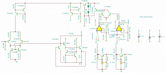
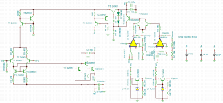
Attached is the circuit made in TINA and also two pictures of the circuit.
Thank you very much for your help,
Best regards,
Daniel Almeida
I'm a newbie in amps design and I'm trying to design a power amplifier based on Bob Cordell's book "Designing Audio Amplifiers" designs.
The problem is I don't have the BUZ900P and BUZ905P models and I can't simulate with the referred devices.
I'm simulating with IRFP240/9240 pair, but I've got some problems, if I increase the Miller compensation capacitor (used to form a Miller integrator at high frequencies) I've a better phase margin, but the slew rate and THD gets worse.
I've also other components influencing this characteristics, the Zobel network which causes overshoot at frequencies if the value of Rz or Cz is to high, and there's also another problem, the gate stopper resistors used to "kill" parasitic gate oscillations, if the value is to low I've danger of oscillations and the phase margin is terrible, If I raise the value I've got again overshoot at high frequencies.
Inicially I tried to leave the power devices without quiescent current, something like a "pure" class B, and this results for the gain margin, but the overshoot it's huge.
I've tried to use Bob Cordell's formula of CMiller = gmLTP/(2*pi*fH*Acl) [F], but this formula seems to be wrong.
Attached is the circuit made in TINA and also two pictures of the circuit.
Thank you very much for your help,
Best regards,
Daniel Almeida
Attachments

Last edited:
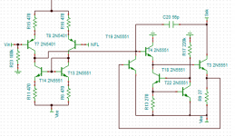
I am concerned about transistor T18 in the emitter follower buffer between IPS and VAS -- see attached image.
The voltage at T18's collector is about 1xVBE, held there by T3's base.
The voltage at T18's base is about 2xVBE, namely VBE(T22)+VBE(T18).
So T18's collector-to-base voltage is about (-1 x VBE). The collector base junction is forward biased.
I think if you want to load T4 with a constant current source, one possible alternative might be an NPN current mirror with mild emitter degeneration. This would meet the constraint of driving T3's base, namely, this alternative would operate correctly with only (1 x VBE) across the current source. Or you could just load T4 with a resistor to Vee as shown in Cordell's and Self's textbooks.
Attachments
VAS stage unstable bias correction
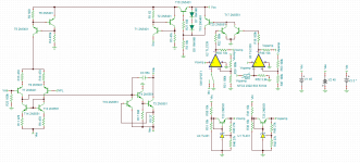
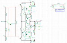
New pics with VAS topology corrected.
But the problem persists
The value of RE has to be 470ohm or 560ohm.
I've got a good simulated THD value for 1 kHz but a poor one for 20kHz
I can only use 56pF or 50 pF(100pF//100pF).
Why the high bias voltage of this lateral MOSFETs seems to be influencing compensation?
Attachments
Last edited:
Hello everyone,
After some simulations, I've the following specifications at +/- 45V:
80 Wrms with Vi = 1,15 Vpp (Acl = 29,9 dB @ 27ºC)
Maximum phase shift measured at output 141 degrees at 27ºC
Thermal shutdown at 120ºC with thermal delay capacitor and a minimum attenuation of -110dB
Vmute (threshold) aprox 2,5 V @ 27ºC
Mute attenuation (minimum) -115dB @ 27ºC
THD1 < 0.003 % at rated power (80Wrms) and 27ºC
THD (20Hz) < 0.008 % at rated power (80Wrms) at 27ºC
THD1 (1-80 Wrms) < 0.03% at 27ºC
THD (20Hz 1-80 Wrms) < 0.008 % at 27ºC
RL tested (4 ohm - 1 Gohm) with aceptable characteristics
Current limiting for 2 ohm loads or less
Short circuit current aprox 3 A (max) at 27ºC (less at higher temperatures)
Quiescent current (max) 20 mA at 27ºC
Problems:
If the values of Rbias resistors (for Qvbe are different from specified values phase shift could be dangerous)
Very high THD20 characteristics 0,5%-0,6% (1-80 Wrms) due to large value of CMiller capacitor which decreases the slew rate at higher frequencies.
Lack of phase margin at 0ºC operation (-165 degrees at 0 dB pole) for both 4 ohm and 8ohm operation.
Could anyone help me solving this problems,
Best regards,
Daniel Almeida
Last edited:
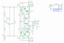
I am concerned that VAS current source T1 supplies about (0.7 / 62) = 11 mA, but resistor R26 conducts about (1.4 / 150) 9.3 mA of that. This only leaves (11-9.3) = 1.7 milliamps for T27, and poor little T21 conducts (1.7mA / Beta) = 17 microamps! I would have thought you'd want more than half of the bias current to flow in (T27 + T21); with the present circuit, only 15% of the bias current flows in (T27 + T21). I also would have thought you'd give T21 its own emitter resistor, guaranteeing that (VBE/Re) flows in T21.
Last edited:
Thank you, so I have to raise the value of the resistors to have less current passing thru them, but about the Darlington Vbe multiplier it's a good idea?
I'm using vertical Mosfets so I need more than 6 V of Vbias, but I think that adding a Re resistor to transistor T21 it's a good idea and I can control the current passing thru T21 adjusting this resistor.
I'm using vertical Mosfets so I need more than 6 V of Vbias, but I think that adding a Re resistor to transistor T21 it's a good idea and I can control the current passing thru T21 adjusting this resistor.
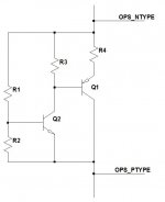
I prefer a to use a Sziklai bias spreader because it is "stiffer" (lower output impedance, dV/dI). This is discussed in Bob Cordell's book, see Fig 14.13(a). I like to include R4 just for extra stability margin; I generally set it somewhere in the range {(5 to 10) / gm_Q1}. But really this is just personal preference; to each their own.
Attachments
Last edited:
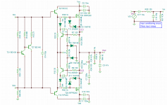
I've corrected the Vbe multiplier and bias resistors now I've only 0,8 mA passing thru both resistors, 1 mA passing thru T21 and 8,2 mA passes thru T28. I've noted a difference in THD levels for 20 Hz and 1 kHz (which are now better) but the slew rate remains low, because I can't lower the value of CMiller without compromising phase margin. Similar problems (to those listed in the other post still occur), when I try to put more quiescent current passing thru the power devices the phase shift aproaches the danger zone.
Do you know some way to solve this problems?
Thank you very much for your help
Best regards,
Daniel Almeida
Do you know some way to solve this problems?
Thank you very much for your help
Best regards,
Daniel Almeida
Attachments
Last edited:

- Status
- This old topic is closed. If you want to reopen this topic, contact a moderator using the "Report Post" button.
- Home
- Amplifiers
- Solid State
- Problems with stability in simulation