Peeceebee heat
Hi All,
I was wondering what the heatsinking capacity should be for the Peeceebee V4.
I just finished building a stereo set using medium size heatsinks 16x6x3,5cm (same I have been using for years with similarly powered 60W P3As).
Peeceebee bias (110ma) and offset (few mV) are set up at nominal 2x35V.
However, bias intensity seems unstable and continues to rise very slowly as well as temperature even without signal.
I stopped the test around 230mA and 55°C.
The sound is great and I would like to continue using it but am concerned about thermal runaway...
Any clues?
Jacques
Hi Magnus.
I don't know which one is better but here in India speaker protection modules are available in diyaudiocart and these seem to work fine.
If you can wait a little more then a diy psu with integrated speaker protection is up next in the menu soon. I will receive the prototypes by tomorrow and PCBs will be available shortly thereafter. Keep an eye on the V4H thread.")
I don't know which one is better but here in India speaker protection modules are available in diyaudiocart and these seem to work fine.
If you can wait a little more then a diy psu with integrated speaker protection is up next in the menu soon. I will receive the prototypes by tomorrow and PCBs will be available shortly thereafter. Keep an eye on the V4H thread.
In warm heatsink condition turn VR3 anticlockwise and trim the bias back to 120mA. From next time on the amp will start with a cold bias of ~80mA and will reach ~120mA slowly as temperature increases and stabilizes
Hi Shaan,
I will try as you suggested, thank you.
I was wondering also if there could be some form of parasitic oscillation in my builds to explain the steady quiescent current increase (happening also while both input and output are disconnected).
Parasitic oscillation is very unlikely if the heatsinks are connected to PSU ground. If you have oscilloscope then probe it, if not turn on the am/fm radio, tune to a clean station, keep it close to amp and turn the amp on. If the station is dead or noisy then its oscillating.
All that said, to me it just looks like a matter of proper trimming as mentioned in last post. All the bests.
All that said, to me it just looks like a matter of proper trimming as mentioned in last post. All the bests.


Assembly story of V4 Rev 2.
I got two PCBs + components from Shaan for a very reasonable price - getting components where i live is impossible. Cant even get a 1N4007 diode!!
Assembling the PCBs was straight forward - the quality of the PCBs is excellent. A couple of suggestions:
- The sequence of soldering suggested in the setup guide is a litte dated. Basic stuff, but solder in order of height (shorter components first)
- The C15 stated in the setup guide is not C15 in Rev 2. It is now C17. C15 and C16 are 220p (the Rev2 mod), either side of VR3 on the board.
- It is easier to set VR1,2,3 to max/min before soldering since it is easier to check they are at max or min (as prescribed). Else you are reliant on the clicks.
- BOTH the P-GND and S-GND need to go the PS ground. I didnt realize this (My bad...Shaan has mentioned that in this forum)
- I soldered a small earth lug to the underside of one of the LATfets. See pic below - one end to the ground trace and the lug hole itself aligned with the LATfet. The heatsink needs to be grounded, and this is an easy way of ensuring that. Make sure the heatsink "is" grounded with a multimeter.

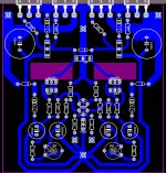
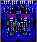
Completed board:
 on heatsink
Singing with test speakers and dual PS. No hum, no cross channel hum

The cage. Self-designed. Got someone to weld it since I dont have a welding set. 490mm x 490mm x 200mm (yeah, spacious)

Realized I needed somewhere to screw the feet onto!! Last minute addition of aluminium cross pieces

Layout without wiring. It fit!! Dual mono config

With wiring completed

PS closeup. Boards from Prasi

Grounding and soft start. I didnt have NTCs to hand (and nowhere to buy out here), so used a 10R resistor. Will replace when I get NTCs

Amp boards (the mounting plate below is slightly out of alignment, which is why the perspex on top looks wonky. Will fix next time I take it apart. The boards are close together, and the power connectors push the board apart. The perspex keeps them aligned and takes the load)

Look forward to any suggestions/corrections. Waiting for the front and back panels.
I got two PCBs + components from Shaan for a very reasonable price - getting components where i live is impossible. Cant even get a 1N4007 diode!!
Assembling the PCBs was straight forward - the quality of the PCBs is excellent. A couple of suggestions:
- The sequence of soldering suggested in the setup guide is a litte dated. Basic stuff, but solder in order of height (shorter components first)
- The C15 stated in the setup guide is not C15 in Rev 2. It is now C17. C15 and C16 are 220p (the Rev2 mod), either side of VR3 on the board.
- It is easier to set VR1,2,3 to max/min before soldering since it is easier to check they are at max or min (as prescribed). Else you are reliant on the clicks.
- BOTH the P-GND and S-GND need to go the PS ground. I didnt realize this (My bad...Shaan has mentioned that in this forum)
- I soldered a small earth lug to the underside of one of the LATfets. See pic below - one end to the ground trace and the lug hole itself aligned with the LATfet. The heatsink needs to be grounded, and this is an easy way of ensuring that. Make sure the heatsink "is" grounded with a multimeter.
Completed board:
on heatsinkSinging with test speakers and dual PS. No hum, no cross channel hum
The cage. Self-designed. Got someone to weld it since I dont have a welding set. 490mm x 490mm x 200mm (yeah, spacious)
Realized I needed somewhere to screw the feet onto!! Last minute addition of aluminium cross pieces
Layout without wiring. It fit!! Dual mono config
With wiring completed
PS closeup. Boards from Prasi
Grounding and soft start. I didnt have NTCs to hand (and nowhere to buy out here), so used a 10R resistor. Will replace when I get NTCs
Amp boards (the mounting plate below is slightly out of alignment, which is why the perspex on top looks wonky. Will fix next time I take it apart. The boards are close together, and the power connectors push the board apart. The perspex keeps them aligned and takes the load)
Look forward to any suggestions/corrections. Waiting for the front and back panels.
Continuing above....
Post setup after an hour of playing: 480mV & 470mV across VAS 47R resistors. 115mA on the MOSFETs. +3mV and -14mV DC offset
However the heatsinks barely get warm even after hours of playing. Suggestions? should I increase the VAS bias? Or replace the LATfet bias diodes and increase the LATfet bias? Or something else?
By the way, it sounds pretty good as is. Soundstage is superb. Mid range/vocals is awesome. Bass seems different from my F5T - the F5T bass seems more rounded/warm, while this seems more clinical. (on Mission M53)
Assembly story of V4 Rev 2.
I got two PCBs + components from Shaan for a very reasonable price - getting components where i live is impossible. Cant even get a 1N4007 diode!!
Assembling the PCBs was straight forward - the quality of the PCBs is excellent. A couple of suggestions:
- The sequence of soldering suggested in the setup guide is a litte dated. Basic stuff, but solder in order of height (shorter components first)
- The C15 stated in the setup guide is not C15 in Rev 2. It is now C17. C15 and C16 are 220p (the Rev2 mod), either side of VR3 on the board.
- It is easier to set VR1,2,3 to max/min before soldering since it is easier to check they are at max or min (as prescribed). Else you are reliant on the clicks.
- BOTH the P-GND and S-GND need to go the PS ground. I didnt realize this (My bad...Shaan has mentioned that in this forum)
- I soldered a small earth lug to the underside of one of the LATfets. See pic below - one end to the ground trace and the lug hole itself aligned with the LATfet. The heatsink needs to be grounded, and this is an easy way of ensuring that. Make sure the heatsink "is" grounded with a multimeter.
Completed board:
Singing with test speakers and dual PS. No hum, no cross channel hum
The cage. Self-designed. Got someone to weld it since I dont have a welding set. 490mm x 490mm x 200mm (yeah, spacious)
Realized I needed somewhere to screw the feet onto!! Last minute addition of aluminium cross pieces
Layout without wiring. It fit!! Dual mono config
With wiring completed
PS closeup. Boards from Prasi
Grounding and soft start. I didnt have NTCs to hand (and nowhere to buy out here), so used a 10R resistor. Will replace when I get NTCs
Amp boards (the mounting plate below is slightly out of alignment, which is why the perspex on top looks wonky. Will fix next time I take it apart. The boards are close together, and the power connectors push the board apart. The perspex keeps them aligned and takes the load)
Look forward to any suggestions/corrections. Waiting for the front and back panels.
Thanks a lot for sharing your build info and also for the points on assembling. Much appreciated.
Continuing above....
Post setup after an hour of playing: 480mV & 470mV across VAS 47R resistors. 115mA on the MOSFETs. +3mV and -14mV DC offset
However the heatsinks barely get warm even after hours of playing. Suggestions? should I increase the VAS bias? Or replace the LATfet bias diodes and increase the LATfet bias? Or something else?
Something else. Turn VR3 and crank it up to 200mA. They'll get warm this time.
The 1N4148 diodes are soft clippers, not MOSFET bias spreaders.
By the way, it sounds pretty good as is. Soundstage is superb. Mid range/vocals is awesome. Bass seems different from my F5T - the F5T bass seems more rounded/warm, while this seems more clinical. (on Mission M53)
Great to hear that!
That clean and uncolored bass was one of my main targets during designing V4. IMHO, players always appreciate a less bumpy ground (depends on the game too, of course). And I believe one of the reason the rest of the spectrum comes out awesome is because the lows are free of bumps i.e. color/warmth.
I love F5T's bass however, heard many times in my friend's Turnberries, and as far as warmth in LF goes, it is hard to beat.
I hope that you will appreciate the difference between the two amps' LF signature. As V4's sound is not supposed to mimic or replace F5T in any shape or form, but just be different.
Thanks again
shaan
- Home
- Amplifiers
- Solid State
- PeeCeeBee