I DO think the parts LC sent out are worth measuring to see how close a complementary pair they make. I can try to do that, because I have not installed them yet, but someone else would have to provide a little direction.
I believe that for this kind of circuit (symmetrical CFB) one needs transistors with high hfe and as closely matched as is realistic. For me, ultra low Cob is not absolute priority, unless one really wants to play a lot with the scope. All you need is DMM that can measure hfe. I think that the best option is to buy a lot of KSA1220/KSC2960, like Jason did, and try to match hfe.
Why don't you measure hfe for transistors that LC delivered with pcbs? I guess that there is greater mismatch than with Jason's 1220/2960 matched pair. I doubt if LC matched them. He simply provided transisitors with the same hfe rank, that's all.
I think I've found my new favourite TO-126 device, these are fast enough for VAS, robust enough for pre driver or even driver in lower power applications, isolated tab for easy mounting, easy to match, relatively high gain. Oh, and reasonably priced at ~$0.20 each in 100 quantity.
I'm able to get a 10% hfe match on about 50 pairs of the KSA1220AY / KSC2960AY, so pretty good. I can get about 20 pairs to less than 3% hfe difference. I do agree that a low-ish Cob is nice, but more like 'icing on the cake' for me too.
I'm able to get a 10% hfe match on about 50 pairs of the KSA1220AY / KSC2960AY, so pretty good. I can get about 20 pairs to less than 3% hfe difference. I do agree that a low-ish Cob is nice, but more like 'icing on the cake' for me too.
I think I've found my new favourite TO-126 device, these are fast enough for VAS, robust enough for pre driver or even driver in lower power applications, isolated tab for easy mounting, easy to match, relatively high gain. Oh, and reasonably priced at ~$0.20 each in 100 quantity.
I'm able to get a 10% hfe match on about 50 pairs of the KSA1220AY / KSC2960AY, so pretty good. I can get about 20 pairs to less than 3% hfe difference. I do agree that a low-ish Cob is nice, but more like 'icing on the cake' for me too.
KSA1220AY / KSC2690AY seem to be intended to perform well at much higher currents/higher power. Using them as a replacement may be a good idea, but I doubt that they will be good drop-in substitutes, without making some other adjustments.
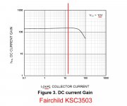
If I remember correctly the SA1381/SC3503 were both quite linear in the same range of collector current, which is about were LC had his VAS circuit biased (showing that he is a Careful Cat, and not just a Lazy one...
 )
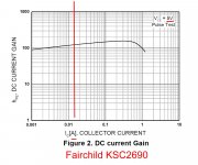
)KSA1220/KSC2960, were not, at least not in the 10-20mA range of bias current. The published "typical" NPN device curve looks fairly steep in our area of interest (certainly when you take into account that the graphs are logarithmic). So, as the base current of the pair changes, the PNP device will be more-or-less linear, but the NPN device, not so much.
The end result may be that the amplifier will sound fine at one volume setting, but when you turn the volume up, or simply when the material played changes, the sound signature you like will change. Personally, I have found this annoying in the past. (Not horribly objectionable, but still...)
One of the things I like about the VSSA circuit, is that it seems to yield an amp that sounds uniformly good no matter what speakers, volume level, or material I try.
Having said all that, I am willing to measure and compare different pairs of transistors, but someone with a bit more knowledge will have to suggest a meaningful test - translation, I do not have the experience to do that on my own.
Attachments
Last edited:
Another issue is when the bias current of the VAS is intentionally changed, or allowed to change with changes in supply voltage. When someone intentionally changes the bias point of the VAS transistors to be lower or higher, or changes the supply voltage without adjusting the VAS bias to stay in the desired range, some additional distortion will result...
This does not mean that we should not use different VAS transistors or different supply voltages... for all I know, it may even sound better...
This does not mean that we should not use different VAS transistors or different supply voltages... for all I know, it may even sound better...
One of the things I like about the VSSA circuit, is that it seems to yield an amp that sounds uniformly good no matter what speakers, volume level, or material I try.
You shall have it with many replacement VAS transistors, including Jasons choice. I think that uniformly good sound quality at different volumes is more cosequence of topology itself than of transistor choice. Many people in this thread built PeeCeeBee with suboptimal transistors (Shaan himself does not have access to first class components) and they still have great sound.
LC used particular transistors because he did not want some competent engineer to criticize his skills, not because VSSA can not sound good with different components.
(I always liked sound of quasi complementary output stages although the mismatch between n and p side is huge. In fact I like it more than the sound of complementary EF.)
But if one can find LCs VAS tranies in the same hfe rank, which is probably impossible now, it's OK. He will have great sound and great specs.
Today I did some tweaking with the emitter degenerators and VAS base to PS resistors, just out of curiosity, to see what happens when...
Replaced the 10R and 470R with 22R and 220R and decreased current injectors to 5K. Supply is +/-28V. Still no Cdom and zobel.
The modded amp is now singing, with noticeable change in the mid-range. The vocals are different. Bass/highs seems the same as before.
more later...
Replaced the 10R and 470R with 22R and 220R and decreased current injectors to 5K. Supply is +/-28V. Still no Cdom and zobel.
The modded amp is now singing, with noticeable change in the mid-range. The vocals are different. Bass/highs seems the same as before.
more later...
hey, Shaan
which is the best for the sound result as your experiment before, the diode in V+/- rail, 1N4148 / Schotky / MUR?
thanks, g.y.w.
1N4148, so far.
Couldn't source MUR. Local stockist out of stock.
Will update once the experiments are done.
(Shaan himself does not have access to first class components)


still have great sound.


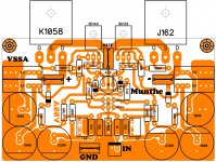
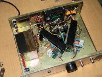
As posted a while ago, I have been working on a Capacitance Multiplier Power Supply, both for Shaan's PeeCeeBee, and for LC's VSSA modules. See post above:
Improved Cap Multiplier Concept
I have no fundamental problems w. using a SMPS, but what fun is it to buy a complete and tested product that will work fine out of the box?
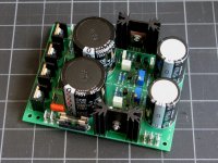
For this, I adapted MrEvil's design for an "Improved Capacitance Multiplier", which uses MOSFETs for pass transistors, and which is capable of providing a clean output with less than 10mV of ripple and noise, using only two electrolytic caps for a total of 15000uF per rail (and probably less).
The pics below show the result. There is more information in MrEvil's thread, including schematic, BOM, test results w. scope screen pics, etc.
Documentation
In the PeeCeeBee spirit, a single-sided layout for those extreme diy'ers who like to etch their own will also be posted in a few days. There are substitutes for all of the components used, and the original designer has stated that the circuit is very tolerant of alternative component choices. There are no expensive parts.
Any questions that relate directly to use with VSSA/PeeCeeBee I will try to answer here, but - please keep any technical discussion of the power supply, components etc. in the other thread, so Shaan can concentrate on this one,
Thank you.
Improved Cap Multiplier Concept
I have no fundamental problems w. using a SMPS, but what fun is it to buy a complete and tested product that will work fine out of the box?
For this, I adapted MrEvil's design for an "Improved Capacitance Multiplier", which uses MOSFETs for pass transistors, and which is capable of providing a clean output with less than 10mV of ripple and noise, using only two electrolytic caps for a total of 15000uF per rail (and probably less).
The pics below show the result. There is more information in MrEvil's thread, including schematic, BOM, test results w. scope screen pics, etc.
Documentation
In the PeeCeeBee spirit, a single-sided layout for those extreme diy'ers who like to etch their own will also be posted in a few days. There are substitutes for all of the components used, and the original designer has stated that the circuit is very tolerant of alternative component choices. There are no expensive parts.
Any questions that relate directly to use with VSSA/PeeCeeBee I will try to answer here, but - please keep any technical discussion of the power supply, components etc. in the other thread, so Shaan can concentrate on this one,
Thank you.
Attachments
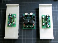
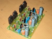
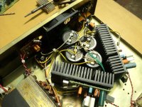
And my 4 year old quasi-complementary LTP VFB system replenished! Now fully Symmetrical and CFB. Yeppiiiiiiiiiiiiiiiiiiiiiiii... 
Doing things still in the cheap way though. Please don't mind the non-standard look.
Doing things still in the cheap way though. Please don't mind the non-standard look.
Attachments
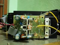
These two beauties going to a local friend!
wow beautiful shaan, are these will powered from +- 40vdc?
and what is the sifgnificant effect of 4.7uf elco instead of 1uf film?
thanks
wow beautiful shaan, are these will powered from +- 40vdc?
and what is the sifgnificant effect of 4.7uf elco instead of 1uf film?
thanks
Thanks naf.
These will be fed from +-30VDC.
With 1uF there is oscillation when PS wires are more than 4" long. With 4.7uF this was solved and the elcos don't seem to affect sonics.
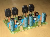
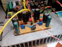
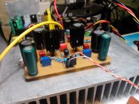
my newest build based on PMI layout fed from diy smps +-40vdcThanks naf.
These will be fed from +-30VDC.
With 1uF there is oscillation when PS wires are more than 4" long. With 4.7uF this was solved and the elcos don't seem to affect sonics.
Attachments
naf: Any comments about how the etching went?
I ask mainly b/c I plan to modify the Cap Multiplier layout for single layer, so anyone can etch it, and if you have any comments on the layout or the pdf I pasted for this board, it might help with the next one.
no problems when etching, i redraw from your layout to fit my part stock. i always redraw with smallest trace 1.3mm width for ease of transfer and etch.
please make layout cap. multiplier on single side board.
thanks for wonderful layout

- Home
- Amplifiers
- Solid State
- PeeCeeBee