...which in fact means unlimited choice of VAS transistors from ubiquitous BD pair to something better...
Won't that be great?

With CFB amps there is no constant gain/bandwidth product. Bandwidth is not dependent on ratio of feedback and gain setting resisitors but on value of feedback resistor. This is very straightforward way of limiting bandwidth and influencing stability. Why should we be limited to 1K/47R values? Lower values improve noise performance of the ciruit but are not beneficial for stability. I've seen even lower values in circuit similar to VSSA (820R/16R) but also with some additional compensations.
I have so far been unable to hear noise with 2K2/100R(well there is tiiiiiiny bit of it with my ear stuck on dome-tweeter.
") But I doubt people normally "listen" to music this way.
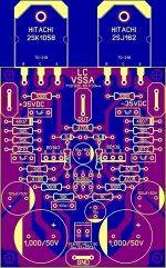
But I doubt people normally "listen" to music this way.BD139/140 have to rotate 180 degree...
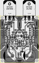
My apologies wiljj. My PCB software was lacking in some models, so had to use the TO220, which led to some confusion. I am learning to use better programs and will replace the attachments with better versions soon. I hope you are still with peeceebee.
If eliminating the gate resistor means adding a 100pf cap, I am not sure what is gained. If you want to leave out the compensation caps completely, and at the same time have to add 100pF elsewhere, and at the cost of a more complicated layout, is there really an advantage?
Exactly.
Well, eliminating the resistors and adding caps might be one of the compromises for designing an ultra-compact dual layer "OEM" pcb
. A few months ago I read somewhere in the net, something that went like - CFB is more "CFB" with lower feedback resistor. Less resistance = more CFB, zero resistance = infinite CFB. 
...I would like to have a board that follows Shaan's basic idea to have a VSSA that anyone can build with parts available almost anywhere...
You already have them don't you? Your own peeceebee, which shaan can build with parts available to him.


Last edited:
Yes,You already have them don't you? Your own peeceebee, which shaan can build with parts available to him.
What I should have said is, if I make changes in the layout as a result of these discussions, I don't want it to be at the expense of the things that made me want to do it in the first place...
PMI!
Tyimo
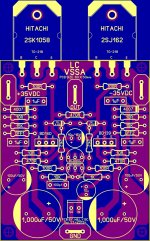
I see in the picture, that you are using only one 0.33R 5W resistor. Are you sure is it enough? In this value it can drive less than 4 ampers.3x 4700uF per rail, in CLCRC passive filter configuration
Tyimo
My apologies wiljj. My PCB software was lacking in some models, so had to use the TO220, which led to some confusion. I am learning to use better programs and will replace the attachments with better versions soon. I hope you are still with peeceebee.
It's alright shaan...
it's my pleasure and i hope i'm welcome here, it make's me feel safe specially with those very kind and helpful fellow diy'ers on this thread that never leave behind when they spot errors for new builders...BTW, trying to improve this PCB and hope it's good to go now...
Regards,
Attachments
Last edited:

It's alright shaan...
BTW, trying to improve this PCB and hope it's good to go now...
Regards,
Yeah! This is another very good pcb for this project, with another mounting option for output fets.
Is the 2.2K resistors not too close to the BDs?? Think about the mini heatflags!
Thanks... maybe this one?
Attachments
Thanks... maybe this one?
That's not really an issue as you can mount 2k2 under board so you have enough room faor heatsink.
Marc
You are correct.PMI!
I see in the picture, that you are using only one 0.33R 5W resistor. Are you sure is it enough? In this value it can drive less than 4 ampers.
Tyimo
A 100% safe resistor value would be 0.2R/5W. Also, the inductor is probably too small to use at continuous full power, and so is the transformer. For best possible performance @ full power & maximum voltage that this amplifier is capable of, you would need two transformers and two power supplies this size, and a much better filter, which is where I am going with my new supply.
However (and please do check my math):
I did not size the power supply components for continuous maximum power. I may do that with my new power supply, but I have to do some testing first.
Even fused at around 1/2 max power level using fast-blow fuses, this setup can get crazy loud in a normal size space (not the point of your q., but that is the reason why I wrote low-to-moderate power above).
As far as the resistor goes, it is a good quality wire-wound 5W resistor, which can easily take 50% more than its power rating for short peak-power use. Not for very long, but long enough (if the fuses do not pop first, saving my eardrums from destruction...
)Transformer is 250VA, 25V AC output, so that gives around 35V DC rail voltage (nominal, and less after diode drop in the bridge). Neglecting all other losses, that would be 125 watts maximum per rail output. So at 35V DC, the current can only reach 125W/35V ~ 3.6A per rail. After that, the transformer field will start to collapse, main fuse will blow, etc, etc...)
So, the maximum power in the resistor would be ~ 4.2 watts, I think.
We can do a similar calculation the other way, in other words, how much peak, and how much continuous power do YOU want to design for, and what will the components have to be?
Related to how you mount the resistors, I wonder if it is worthwhile to bring up the single heatsink (again) for the pair of VAS transistors.That's not really an issue as you can mount 2k2 under board so you have enough room faor heatsink.
Marc
LC has everything mounted to the one large heatsink, so the issue does not arise.
I did originally design my board for this, but I could not tell any difference, with my ears, or on the oscilloscope, when I first tried it. After that, I got busy testing other things... (and the individual heatsinks are more convenient)
As an aside, I see a temp rise of 20-22C above room temperature, measured on the case of the transistor, with a small u-shaped heatsink.
Related to how you mount the resistors, I wonder if it is worthwhile to bring up the single heatsink (again) for the pair of VAS transistors.
LC has everything mounted to the one large heatsink, so the issue does not arise.
I did originally design my board for this, but I could not tell any difference, with my ears, or on the oscilloscope, when I first tried it. After that, I got busy testing other things... (and the individual heatsinks are more convenient)
As an aside, I see a temp rise of 20-22C above room temperature, measured on the case of the transistor, with a small u-shaped heatsink.
That's right but through doing that he was necessary to add temp. compensation (not sure it's the right word) through TLV431 adding...so not in Shaan initials statements....
Marc
Last edited:
Yes, I remember. I read most of that thread, but it is easy to misunderstand the reason why something was done (for me anyway).That's right but through doing that he was necessary to add temp. compensation (not sure it's the right word) through TLV431 adding...so not in Shaan initials statements....
Marc
The temperature of the VAS transistors can rise very quickly. It will stabilize at a reasonable level, even with a single small-ish heatsink, but it changes much faster than the temperature of the big heatsink with the mosfets, and so does the bias current.
Yes, it looks better. Did you checked all the components in the reality, how much space are they need?Thanks... maybe this one?
It is a good idea.That's not really an issue as you can mount 2k2 under board so you have enough room faor heatsink.
Btw: your pcb looks very nice.
Hi PMI!
There are different rules....
Greets:
Tyimo
I understand you. I was asking this because I am coming from the class A world.Transformer is 250VA, 25V AC output, so that gives around 35V DC rail voltage (nominal, and less after diode drop in the bridge). Neglecting all other losses, that would be 125 watts maximum per rail output. So at 35V DC, the current can only reach 125W/35V ~ 3.6A per rail. After that, the transformer field will start to collapse, main fuse will blow, etc, etc...)
There are different rules....Greets:
Tyimo
Related to how you mount the resistors, I wonder if it is worthwhile to bring up the single heatsink (again) for the pair of VAS transistors.
I think that two small U shaped heatsinks is very practical solution and it is much easier to buy them than to make and drill single one.
Isn't peak current greater than 3.6A, somewhere near 8A?Transformer is 250VA, 25V AC output, so that gives around 35V DC rail voltage (nominal, and less after diode drop in the bridge). Neglecting all other losses, that would be 125 watts maximum per rail output. So at 35V DC, the current can only reach 125W/35V ~ 3.6A per rail. After that, the transformer field will start to collapse, main fuse will blow, etc, etc...)
Last edited:
You mean during the short time the caps charge through the bridge, or maximum current through the filter resistor, averaged over several AC cycles?Isn't peak current greater than 3.6A, somewhere near 8A?
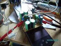
HV test...
Me finally back home(this time to stay)... 'been six long months wandering... 
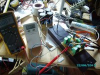
Back to test bench and connected my +/-35V PS to peeceebee.
(Changes: "U" shaped heatsinks for VAS, two parallel 33K as current sources on each side(13mA VAS+input, 190mA total, offset 5mV), FB cap reduced to 1000uF, added zobel(oscillation with speaker cable(3meter long))).
Result: Nothing special.
Me finally back home(this time to stay
)... 'been six long months wandering... Back to test bench and connected my +/-35V PS to peeceebee.
(Changes: "U" shaped heatsinks for VAS, two parallel 33K as current sources on each side(13mA VAS+input, 190mA total, offset 5mV), FB cap reduced to 1000uF, added zobel(oscillation with speaker cable(3meter long))).
Result: Nothing special.
Attachments
- Home
- Amplifiers
- Solid State
- PeeCeeBee