Second channel has passed the test too, 6mV DC offset a little bit lower bias and I feel this one has nicer sound
Same types and values of components and same circuit and same layout but different sound?!
Please upload pics of both boards... lots of pics.
Lots of pics
They are tested & I will drill the heat sink, prepare PSU, etc,... anything that need to do
Now it time to share what I made
Thank you Shaan, Lazy Cat, PMI, Naf & everyone that support me
see you soon
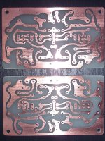
I want to give it a name: VSV PeeCeeBee
PeeCeeBee size 50 mm * 84 mm a bit smaller than your ID card
Maybe just my feeling
Same types and values of components and same circuit and same layout but different sound?!
Please upload pics of both boards... lots of pics.
They are tested & I will drill the heat sink, prepare PSU, etc,... anything that need to do
Now it time to share what I made
Thank you Shaan, Lazy Cat, PMI, Naf & everyone that support me
see you
soonI want to give it a name: VSV PeeCeeBee
PeeCeeBee size 50 mm * 84 mm a bit smaller than your ID card
Attachments
-
bottom JB VSSA.pdf36.7 KB · Views: 452
-
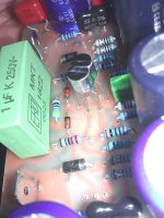 Input pair close up.jpg113.4 KB · Views: 739
 -
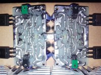 bottom side.jpg169.2 KB · Views: 808
 -
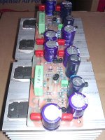 Landscape.jpg142.7 KB · Views: 1,418
 -
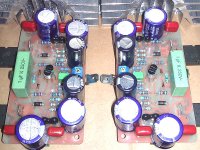 Same.jpg222 KB · Views: 1,513
 -
 Potong balok D.JPG85.6 KB · Views: 1,559
 -
 PeeCeeBee.jpg178.8 KB · Views: 1,640
 -
 DipTrace PCB - VSSA.gif81.3 KB · Views: 1,694
Last edited:
@John: Everything looks really good!
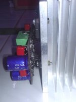
Just one Q: I see the drivers on the bottom of the board, but what keeps them in contact with the heatsink, in other words, how are they attached or pressed to the heatsink?
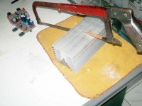
P.S.: I can't believe you managed to cut that heatsink by hand... OMG!
Just one Q: I see the drivers on the bottom of the board, but what keeps them in contact with the heatsink, in other words, how are they attached or pressed to the heatsink?
P.S.: I can't believe you managed to cut that heatsink by hand... OMG!
Last edited:
Shaan, when I first got second channel working, I could swear they sounded different too. I even swapped channels to make sure.Same types and values of components and same circuit and same layout but different sound?!
Not sure why, but after a day or so, and after I re-calibrated the bias and offset, they seemed to sound the same. It could be electrolytic caps taking a bit of time to settle, or maybe something was off because I did not set them up at the same time. Or, it could just be listening to one channel for a week...
I believe that LC posted somewhere that new caps needed 50 hrs to "bed in", and he is using super-premium elcos. I am using the Panasonic FR-series in the first two boards (low ESR @ low cost).


Maybe just my feeling
They are tested & I will drill the heat sink, prepare PSU, etc,... anything that need to do
Now it time to share what I made
Thank you Shaan, Lazy Cat, PMI, Naf & everyone that support me
see you
I want to give it a name: VSV PeeCeeBee
PeeCeeBee size 50 mm * 84 mm a bit smaller than your ID card
Ooh, nice. Very 'organic' looking like PCBs used to be done in the '70s. May I ask what VSV stands for?
More pictz
or maybe I have too strong muscle
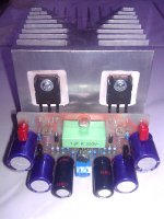
BTW Here how the vas tranie sit on the heat sink
but from the top only, bottom view not so good at all...
I like to do PCB like that feel like old school day
Shaan, I post two more pictz hope that's okay
one channel done, the other next day maybe ...
Nothing impossible@John: Everything looks really good!
Just one Q: I see the drivers on the bottom of the board, but what keeps them in contact with the heatsink, in other words, how are they attached or pressed to the heatsink?
P.S.: I can't believe you managed to cut that heatsink by hand... OMG!
or maybe I have too strong muscle BTW Here how the vas tranie sit on the heat sink
Hi Jason, Very Symmetrical ViewOoh, nice. Very 'organic' looking like PCBs used to be done in the '70s. May I ask what VSV stands for?
but from the top only, bottom view not so good at all...
I like to do PCB like that feel like old school day
Shaan, I post two more pictz hope that's okay
one channel done, the other next day maybe ...
Attachments
Last edited:
Same types and values of components and same circuit and same layout but different sound?!
This is probably due to new elco-s. There is a way to form elco-s before soldering them. Some people use small 7815 regulators to charge elco at 15V for about 15 minutes. Then elco is discharged through high power resisitor. After that elco is again charged for 15 minutes at voltage close to nominal voltage and again discharged through high power resistor. It is even better to use lab supply for forming of elcos because some elcos are rated only 6V or 10V.
It is claimed that this forming also make elcos last longer.

Concerning elcos, a friend of mine who is in repair business for a long time, just reminded me that until elcos are fully formed various kinds of strange behavior are possible, including offset drift and even bias drift. No matter how good or expensive elcos are used, when new they will leak a little until fully formed. Especially critical are ones in NFB loop, 2200uF in this case.
Therefore, allow amp some time to achieve this equilibrium.
Therefore, allow amp some time to achieve this equilibrium.
Maybe just my feeling
They are tested & I will drill the heat sink, prepare PSU, etc,... anything that need to do
Now it time to share what I made
Thank you Shaan, Lazy Cat, PMI, Naf & everyone that support me
see you
I want to give it a name: VSV PeeCeeBee
PeeCeeBee size 50 mm * 84 mm a bit smaller than your ID card
I will slowly build PeeCeeBee design of Mr. Jhon
When stored, or unused, not just when new, they will leak a lot, like 10000times more leakage than when fully re-formed................ No matter how good or expensive elcos are used, when new they will leak a little until fully formed..........
Re-forming of test samples is a standard adopted by ALL manufacturers immediately before starting the measuring of parameters.
That would argue against just letting the board warm up, setting the offset, and then removing/replacing the trim pot with a permanent resistor....Especially critical are ones in NFB loop, 2200uF in this case... Therefore, allow amp some time to achieve this equilibrium.
That would argue against just letting the board warm up, setting the offset, and then removing/replacing the trim pot with a permanent resistor.
Yes, I think when board is made in such way to include trim pots, they should remain there. Also, after several years of work there will probably be some drift in resistors and other components, so it is nice to have an easy method of compensating offset. In this case I prefer the board that you designed because it has trim pot!
That is probably the best approach. However, the rail caps and the input cap won't change the setup, I think. The 2200 uFd cap just might.Or re-form all critical electrolytics BEFORE you solder them into your assembly.
Timing caps, audio coupling caps, biasing caps, DC blocking caps, HV caps, etc.
I am aware of electrolytic caps' characteristics changing, and settling over time. I do NOT have any previous experience comparing two boards on separate channels that were built a few days apart.
I assume it will be difficult to compare test results in this thread, since we are all using different components...
In other words, any suggestions you may have will probably be helpful here.
Last edited:
Thank you, kind of you to say that! I am looking forward to some feedback when someone has built and listened to it!Yes, I think when board is made in such way to include trim pots, they should remain there. Also, after several years of work there will probably be some drift in resistors and other components, so it is nice to have an easy method of compensating offset. In this case I prefer the board that you designed because it has trim pot!
Or re-form all critical electrolytics BEFORE you solder them into your assembly.
Timing caps, audio coupling caps, biasing caps, DC blocking caps, HV caps, etc.
Andrew T
You are right 100 % ,
BTW , from many years of my experience Elko`s with lower ratings voltage is more critical than same Elkos with higher voltage for same reforming issue , but also for final operative life to , so I suggest that both 2200uF GNFB Elkos to have 16VDC ratings as optimum value , 105 C rated is not bad choice to .
Best Regards to All !
( Repair Man )
- Home
- Amplifiers
- Solid State
- PeeCeeBee