O.K. No problem, but now you should answer!
Ca. what is the value for ca. 400-600mA? The original has ca. 160mA bias.
Hi Tyimo

Well if you're using 2SJ162 and 2SK1058 pair, between both gates there should be something around 2,5 V to 3,5 V to get 400-600 mA drain bias current. For that purpose you can experiment a little and learn a lot by doing so.

First you can try resistive only bias spreader, like 1 k trimmer and 1,5 k resistor in series.
Secondly five 1N4148 diodes plus 500 Ohm trimmer in series.
Thirdly 2,4 V zener diode alone or with 500 Ohm trimmer in series.
You could even try Vbe multiplier with NPN BJT and at last but not the least TLVH431 shunt regulator.
Each of this versions would also need a shunt 1 uF capacitor from gate to gate.
")
The most stable bias would, without any doubt, provide you 431 shunt regulator, but in any case 400-600 mA should be set only with proper heatsink in mind.

I'm building two stereo amplifiers to feed a pair of floor standing Usher 604 'speakers, in a biamplification setup.
WOW
would like to see pic and comments Any Q., please ask.
First, congratulations, very clean and professional built, size of PCB enables you to experiment with exotic parts too.
And the Q: What is your intention to produce so many channels? What kind of speakers will be connected to?
Thanks, hoping to do just thatFirst, congratulations, very clean and professional built, size of PCB enables you to experiment with exotic parts too.
And the Q: What is your intention to produce so many channels? What kind of speakers will be connected to?
Modified (and old) Boston Acoustics speakers, Slightly newer B&W 602 (03?), very old set of restored/modified JBL speakers... nothing too exotic. I may have to trade one of my cars in for a better set one of these days...
From experience, I learned to build more than one of anything before I am completely happy with it, and it is very hard to compare if you no longer have the previous version to listen to. If all works out well, I am hoping to use both sets, and perhaps build one set into a multi-channel configuration.
Two sets are going to friends who who are helping with other parts of the project. One person who has been reading this thread has asked for a set... couple spares, for when I make a mistake, or for anyone else who is interested... so, not that many, really.
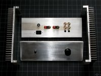
I attached an example of what the test chassis may look like, machined, but not "finished" in this pic (heat sinks from Heatsink USA, 10"x4" w. 1" fins on 0.33 base, 0.65C/W).
Attachments
Thanks LC. So It's mean that with a simple 1K trimmer it will be still under 400mA?Well if you're using 2SJ162 and 2SK1058 pair, between both gates there should be something around 2,5 V to 3,5 V to get 400-600 mA drain bias current. For that purpose you can experiment a little and learn a lot by doing so.
First you can try resistive only bias spreader, like 1 k trimmer and 1,5 k resistor in series.
Greets:
Tyimo
Thanks LC. So It's mean that with a simple 1K trimmer it will be still under 400mA?
Greets:
Tyimo
It depends how high is VAS bias current.
If VAS bias is set to 15 mA you would need to set the trimmer to 234 Ohm to get 3,5 Vgg, so at that point output bias would be 600 mA. Yes 1 k trimmer would do OK.
Payment sent by bank transfer.
Thanks for everything!
George
Hi George
You mean for VSSA? Thanks.
Shaan will be "happy"
Thanks LC!!!It depends how high is VAS bias current.
If VAS bias is set to 15 mA you would need to set the trimmer to 234 Ohm to get 3,5 Vgg, so at that point output bias would be 600 mA. Yes 1 k trimmer would do OK
Test Results
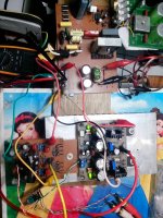
So far I am getting good test results w. the first board I have assembled.
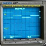
Clean sine wave, well behaved when clipping, nice square wave to about 100KHz with no visible ringing. Most of the overshoot visible in some of the tests comes from a corresponding trailing edge overshoot in the source signal. This is especially obvious in the last pic.
Since the basic design was already tested by Lazy Cat and by Shaan, my goal is to run a few simple tests to make sure the first board is behaving well, and that I have not created any problems in layout, or in component selection.
The board as tested has an input filter, 47pF compensation at the drivers, and no Zobel installed. Power supply rails are set to a nominal +/-35V (36V measured), with the help of a variac which feeds the transformer. Total bias current settled at around 145 mA with the two diodes installed, and with no additional parts (no 470R). DC offset was set and checked at 0V before the test, but does drift a few mV with rising temps during the test. Gain was set to 10, basically for my convenience and test equipment.
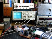
Signal source: Wavetek 182A
Oscilloscope: Tektronics 2221A 100MHz Analog/Digital Storage Scope
Meter: Fluke 77
Power Supplies: Tektronix PS280 bench supply, and Transformer/rectifier/filter per Shaan's definition of what might be used with a through-hole version of VSSA.
First pic is a shot of the test setup.
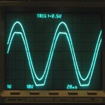
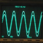
#2 and #3 show a 20KHz sine wave, just below and just above clipping. My goal here was to check that the output matches the input up to maximum voltage, and then clips cleanly.
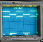
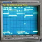
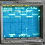
#4 and 5 are a 20KHz and 50KHz square wave, shown in non-storage mode.
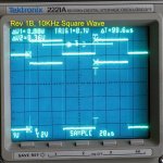
#6, 7 and 8 are square waves at 10, 20 and 50KHz in storage mode. 50KHz rise and fall times are starting to deviate from the input signal.
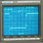
#9 is a rough measurement of the rise time achievable with the component values as installed, which can be used to estimate slew rate and the bandwidth limit of the amplifier.
So far I am getting good test results w. the first board I have assembled.
Clean sine wave, well behaved when clipping, nice square wave to about 100KHz with no visible ringing. Most of the overshoot visible in some of the tests comes from a corresponding trailing edge overshoot in the source signal. This is especially obvious in the last pic.
Since the basic design was already tested by Lazy Cat and by Shaan, my goal is to run a few simple tests to make sure the first board is behaving well, and that I have not created any problems in layout, or in component selection.
The board as tested has an input filter, 47pF compensation at the drivers, and no Zobel installed. Power supply rails are set to a nominal +/-35V (36V measured), with the help of a variac which feeds the transformer. Total bias current settled at around 145 mA with the two diodes installed, and with no additional parts (no 470R). DC offset was set and checked at 0V before the test, but does drift a few mV with rising temps during the test. Gain was set to 10, basically for my convenience and test equipment.
Signal source: Wavetek 182A
Oscilloscope: Tektronics 2221A 100MHz Analog/Digital Storage Scope
Meter: Fluke 77
Power Supplies: Tektronix PS280 bench supply, and Transformer/rectifier/filter per Shaan's definition of what might be used with a through-hole version of VSSA.
First pic is a shot of the test setup.
#2 and #3 show a 20KHz sine wave, just below and just above clipping. My goal here was to check that the output matches the input up to maximum voltage, and then clips cleanly.
#4 and 5 are a 20KHz and 50KHz square wave, shown in non-storage mode.
#6, 7 and 8 are square waves at 10, 20 and 50KHz in storage mode. 50KHz rise and fall times are starting to deviate from the input signal.
#9 is a rough measurement of the rise time achievable with the component values as installed, which can be used to estimate slew rate and the bandwidth limit of the amplifier.
Attachments
-
 Rev1B_1V20KN.jpg174.8 KB · Views: 561
 -
 Rev1B_sin_clip.jpg131.7 KB · Views: 586
 -
 Rev1B_sin_max.jpg126.8 KB · Views: 646
 -
 Rev1B_BW_test1.jpg267.2 KB · Views: 747
 -
 Rev1B_1V50KN.jpg163.2 KB · Views: 142
 -
 Rev1B_1V10K.jpg155.7 KB · Views: 130
 -
 Rev1B_1V20K.jpg172 KB · Views: 131
 -
 Rev1B_1V50K.jpg173.9 KB · Views: 143
 -
 Rev1B_Slew_rat1.jpg867.9 KB · Views: 170
90V/uS if I'm not wrong.
A second look at the dT makes me think that may be I was wrong indeed. The slew rate is at least 5 times that!
Well, I posted the best pic I had, not necessarily the pic of the best test result... This is an old-style storage scope, so capturing the waveform you want to measure, and then ALSO getting a nice picture of it, is sometimes a bit too much for my patience...Hmmm, 90V/uS if I'm not wrong.
In some tests, maximum, calculated from middle 80% of the slope, is well over 100V/usec. The two cursors you see (the x and the boxed x) are used to calculate the figures, the delta V and delta T on the screen.But, from previous experience, I think the usable slew rate (for audio) is around 30-50% of the slew rate measured in this way.
In any case, there will not be a bandwidth limit with this design...
I think so, I played some jazz with good percussion, and it sounded quite nice. I am happy with the sound.PMI, is this slew rate enough for a sharp hit on the snare drum? What do the speakers say?
I only have one channel connected at a time so far, but everything I have tried has tested (and sounded) very very good. Exceptionally clean and crisp highs. I will have some time to test in the next 2-3 days, but until now, only an hour here and there.
In normal listening, the heatsink temperature only rises about 10-15% above room temperature. However, when I intentionally drive the output into clipping or close, the temperature starts to rise gradually, and does NOT level off. So, for anyone else who wants to test like this - please use some caution, and perhaps a small fan.
- Home
- Amplifiers
- Solid State
- PeeCeeBee