Don't think this should be an audible problem even w/o the new power supply. Not if you are using the same on-board caps I am.It probably is less of an issue with capacitance multiplier PSU. (I hope I don't have to replace 1N4007 on my board, but I have a quantity of ultra-fast UF4007 if they are needed)
If I remember correctly, by the time I switched to a conventional 3x4700uF configuration with CRC or CLCRC, that diode was always on at power levels that correspond to normal listening volume.
@Shaan, correct me if I am wrong, I can check this again.
Maybe we should call Jason's version PeeCeeBee "Turbo"

Hmm, maybe. I've just begun to layout a parallel TO3 board and am thinking about a passive bootstrap to allow for increased gate drive to improve voltage efficiency. Any thoughts? Would still be a PeeCeeBee, just pumped up a little. Couple this with some of the dual die Exicons...
I think it is certainly worth a shot, and I like the idea of trying these. The dual die Exicons are a cool part on paper, but I have never had any in my hands. We may be starting to deviate from the original concept with these though... I think they are a fairly pricey part, and not universally available.Hmm, maybe. I've just begun to layout a parallel TO3 board and am thinking about a passive bootstrap to allow for increased gate drive to improve voltage efficiency. Any thoughts? Would still be a PeeCeeBee, just pumped up a little. Couple this with some of the dual die Exicons...
Don't get me wrong here, I'm not suggesting that the dual die Exicons would be the preferred device, just that it could be a pretty capable little beast with them. To the contrary, I'm still very much on board with the original concept.
There was some very early interest in paralleled devices and it seems perhaps a logical step to take. Also, the idea of using a bootstrap arrangement can make the amp a little more voltage efficient.
I'll post my current idea shortly.
There was some very early interest in paralleled devices and it seems perhaps a logical step to take. Also, the idea of using a bootstrap arrangement can make the amp a little more voltage efficient.
I'll post my current idea shortly.
I don't think I know enough to give you some useful comments on the circuit. I like the concept though.Looking at going down a road a little like this... Any thoughts?
In general, two devices per rail, with at least some options, is likely to be more accessible to most people, than a dual-die Exicon.
Having said that, the dual die devices are very attractive, a single layer board layout and heatsink mounting is easier, and there is the potential for making one board so it can acomodate a single mosfet, or dual.
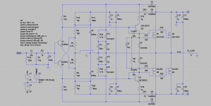
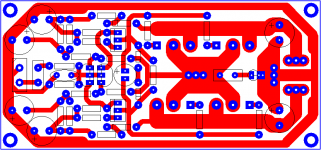
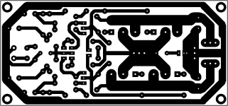
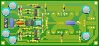
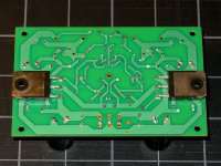
Double-Output PeeCeeBee Draft
This is my plan...
Dimension: 4.3" x 2"
Please comment.
Thanks.
shaan
edit: Underboard FET mount.
This is my plan...
Dimension: 4.3" x 2"
Please comment.
Thanks.
shaan
edit: Underboard FET mount.
Attachments
Last edited:
This is my plan...
Dimension: 4.3" x 2"
Please comment.
Thanks.
shaan
edit: Underboard FET mount.
I like it very much. Nice and compact and I like the power connections together like you have done.
Any comment on the idea of bootstrapping the IPS and VAS to get a PeeCeeBee to swing closer to the rail? Simulation suggests getting about 5V closer to the rails. With 40V rails and no bootstrap clipping occurs at 68W (33Vp into 8 ohm) and with bootstrap clipping begins at 90W (38Vp into 8 ohm). Doesn't sound like much, but headroom is headroom and only takes a few passive components to get it.
Shaan, please ada optional compesation cap. on vas incase somebody want to use ksa/ksc/sa/sc transistor.
Okay.
I like it very much. Nice and compact and I like the power connections together like you have done.
Thanks.
Any comment on the idea of bootstrapping the IPS and VAS to get a PeeCeeBee to swing closer to the rail? Simulation suggests getting about 5V closer to the rails.
I haven't tried the bootstrap config you posted so can't make solid comments. However, there are two more diodes in each rail demanding their own switch-off noise to be atennuated - one more capacitor per rail. Also, being a positive feedback node the bootstrap is prone to invite oscilation, if not implemented correctly, meaning we need scopes.
That aside, it's great to see new possibilities explored.
Shaan what is , other than price and availability, choosing 2 // latfet per rail than a double die as ALFET ALF16N16W with background off place saving and no matching needed?
Marc
Better dissipation, more space between FET leads, ease of drawing amateur layouts, peace of mind etc. You know, we average diy-ers often make bad thermal coupling and demand most from the least. Makes us different.
It seems that the Exicons are a slightly different package/pin spacing than the Renesas parts. I am planning to make a small revision of my circuit board, and I was hoping to accomodate that package, but there is another small issue. As far as I know, those parts do not have internal protection diodes, so those should probably be added to any layout.Shaan what is , other than price and availability, choosing 2 // latfet per rail than a double die as ALFET ALF16N16W with background off place saving and no matching needed?
Marc
I believe that those parts, just like the Alfets, are intended to be used with a faster pair of drivers (at least the Profusion web site seems to suggest that), so I think that would also mean compensation resistors, and carefully chosen gate resistor values. I have done some of that on my board already, but it seems not to be necessary if one is to follow Shaan's schematic and logic in chosing parts.
The boards I have build with close to the component selection published at the beginning of this thread seem to have identical sound to the second set, which uses "better" parts. (Even when I have taken the amp to a couple friends with better speakers).
I see some differences on the o-scope, but not much with my ears. I plan to compare to LC's modules as soon as I have a suitable "home" for them...
Exicons and Alfets do not seem to be easily available in the US from conventional distributors - If you or anyone else has an idea where to get them, plese post it or pm me, thanks...
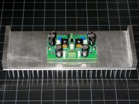
Hey! I may have made bad thermal coupling decisions in the past (well, I am pretty sure of it), but I am "in recovery" now. ...and btw, I am quite proud of my 12-dollar heatsinks. I'll be a bit sad when I finally have them anodized, it will spoil the industrial look......we average diy-ers often make bad thermal coupling and demand most from the least. Makes us different.
I would also say that even though I have made a few changes to my test board set over the last few weeks, the version I listen to almost every day is pretty close to the original schematic published here, and with a smaller heatsink than the one shown below.
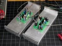
I plan to use the same heatsink, 0.65C/Watt with the VSSA modules from Lazy Cat. Although the chassis may look slightly different, the heatsink corner pieces allow it to be thermally coupled to the front and back, so the overall dissipation will be about what LC specified, despite the compact chassis and smaller/cheaper heatsinks.
Attachments
Looks like the board would have to be extended about 5 mm on either side, even if everything else stays the same.Yes PMI
- renesas => TO3P package
- ALF16N16 => TO264 package same as MJL bipo; bigger than To247
Marc
Attachments
- Home
- Amplifiers
- Solid State
- PeeCeeBee