...has anyone in these very long VSSA/SSA threads compared the Renesas parts to anything else, be it the Alfet, or the Exicon part?
LC seem to be the only one who has built and tested latFET and BIGBT o/p stages. And his choice for the SSA is the latter. VSSA? Dunno...
I haven't used any other o/p devices for SSA/VSSA other than the Renesas pair. They are good; but the performance of a FET with 900pF of Ciss and 1ohm of on resistance depends on how robust the drive stage and feedback node are. Sound from my speaker has so far not shown any funny side of them, I expect they are driven well.
Haven't tried other o/p devices with VSSA, so making a comment will be pointless.
This is my first experience with this circuit topology (meaning almost completely symmetrical). In the past the choice of other components (drivers etc.) seemed to make more difference than output devices, assuming similar specifications.
Do you have any suggestions for any other tests I could try with a DMM and o-scope, besides what I already posted above, or something else to try with a second set of boards?
Do you have any suggestions for any other tests I could try with a DMM and o-scope, besides what I already posted above, or something else to try with a second set of boards?
I'm already at my limit of knowledge... Sorry PMI I disappointed you.
I don't own a scope. My boring posts reflect only the time spent with these amps and observation based on simple and cheap measurements, I love to share what I find to be good. Also I don't have an engineering degree. I'm an arts student, bachelor of English, and a classical traditional drummer.
I don't own a scope. My boring posts reflect only the time spent with these amps and observation based on simple and cheap measurements, I love to share what I find to be good. Also I don't have an engineering degree. I'm an arts student, bachelor of English, and a classical traditional drummer.
Last edited:
Of course not, Shaan! What you write here is anything but that. After all, w/o you and this thread, I seriously doubt I would have built this circuit...I'm already at my limit of knowledge... Sorry PMI I disappointed you.
")
Besides, some of my best insights into sound have come from musicians, something I am sadly NOT! (One of them happens to be a retired professor who used to teach percussion at the local UW-Milwaukee)
I'm already at my limit of knowledge... Sorry PMI I disappointed you.
I don't own a scope. My boring posts reflect only the time spent with these amps and observation based on simple and cheap measurements, I love to share what I find to be good. Also I don't have an engineering degree. I'm an arts student, bachelor of English, and a classical traditional drummer.
Shaan,
When I was young I've been told that people in India have superior hearing compared to us westerners because they have quarter tones in their scales, something that is very difficult for us to hear. Since this is diyaudio your experiences with this particular circuit are much appreciated. I believe more to your ears than to any scope in this world.
Regards
Ivan
Hi PMI,This is my first experience with this circuit topology (meaning almost completely symmetrical). In the past the choice of other components (drivers etc.) seemed to make more difference than output devices, assuming similar specifications.
Do you have any suggestions for any other tests I could try with a DMM and o-scope, besides what I already posted above, or something else to try with a second set of boards?
what about if you do like I do, put your parts as post #1(no caps at B-C VAS transistor & only 4 big elcos) & see what will happen on your scope
Hi Shaan, thanks & I did it safelyWe need,
1. A digital multimeter.
2. 1R/1W x 2.
3. 22R/2W x 2.
For first time power-up solder two 22R/2W resistor to the PS rails, one end of each of them to each rail. Connect the PS to the open ends and turn on power. If nothing explodes/smokes then replace both of the 22R with 1R/1W and connect the PS again, but don't power it up instantly.
Take notes for the measurements from now on.
Set your digital meter to 'mV' and connect the probes to both ends of one of the 1R resistors. Turn on power. Check meter reading. That number shows total Quiscent current Iq.
Measure the front end plus VAS current I(f v) by probing the voltage at the ends of the 10R after the 4007 diodes.
Measure VAS current I(vas) by probing the voltage at the ends of the 10R at their emitters.
Now,
Total current= Iq
Front VAS current= I(f v)
VAS current= I(vas)
So, from aquired data we get,
Front end current= I(f v) - I(vas)
and
FET current= Iq - I(f v)
I hope this will be helpful.
shaan
here the result with +/-30v :
@ 22R = about 2volt & it is okay so
I change to 1R (the current quite low nothing warm)
@ 1R = 140mV (155mV) --->140mV on CH1 & 155mV on CH2
@ 10R (f v) = 99mV (89mV)
@ 10R (vas) = 63mV (56mV)
DC offset = 6mV (1mV)
When I test it input shorted to ground, not use caps at VAS transistors & no zobel at output only 8.2R resistor as load because without load I can't measure DC offset.
I will add zobel latter maybe if that cause it
Do you think it is all okay?
I think the voltage to low because you suggest 35v if we use 15k & not adjusted yet because only my first test
I want to prepare PSU for my PeeCeeBee then test it again with some suggestion from you all
Regards
Last edited:
This makes no sense...................... at output only 8.2R resistor as load because without load I can't measure DC offset............../
DC offset at the output is measured with shorted input and open output.
You can specify a specific Rs, say 100r or 1000r, and state the output offset for this condition, but this is non standard and needs to be specified fully for us to understand.
What I mean is without any load at output DC offset not stable,This makes no sense.
DC offset at the output is measured with shorted input and open output.
You can specify a specific Rs, say 100r or 1000r, and state the output offset for this condition, but this is non standard and needs to be specified fully for us to understand.
maybe oscillation that what I got there, that's why ask here.
At no load at output or open output my DMM can't read the DC offset...
With one 8R2 resistor at output my DMM reading 6mV and 1mV.
When I measured it there was no zobel on output
kang Naf, with or without Zobel?It's strange bli John, i could measured dc offset without load and it sould be done before conneced to speaker
and with 22pF on VAS transistor right?
Last edited:
@John Bali:Thanks for the tip, but.... naaah, I'll skip that test .
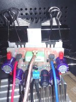
I tested my boards without zobel installed, with 44pF compensation caps, and with the six elcos as shown in the pics. Even with the 44 pF, I measured a maximum slew rate of around 100V/usec. Plenty for me, and I will try 22pF when I compare to the boards from the VSSA GB.
The DC offset does drift a bit with time and temperature, but only a few mV. No sign of any instability or oscillation, at least not so far.
I will repeat some of the tests when I build a second set of boards, but I consider the design as "tested" by LC and by Shaan. So, my goal is to make sure I did not "break" their circuit through some oversight on my part.
.I tested my boards without zobel installed, with 44pF compensation caps, and with the six elcos as shown in the pics. Even with the 44 pF, I measured a maximum slew rate of around 100V/usec. Plenty for me, and I will try 22pF when I compare to the boards from the VSSA GB.
The DC offset does drift a bit with time and temperature, but only a few mV. No sign of any instability or oscillation, at least not so far.
I will repeat some of the tests when I build a second set of boards, but I consider the design as "tested" by LC and by Shaan. So, my goal is to make sure I did not "break" their circuit through some oversight on my part.
Some of my best insights into sound have come from musicians...
Yes, only a musician can teach what to listen for in the music...
...people in India have superior hearing compared to us westerners...
I'v never heard that. But appreciate the complement very much.
Pete and Ivan, thank you guys for your encouragement and support. You are genuinely good people.

At no load at output or open output my DMM can't read the DC offset...
What does the meter show then? The number '1' on the left sidd of the screen? If so, then try setting the range to 'volts' instead of 'millivolts' and see if it shows some reading.
High or unstable offset without load isn't normal and indicates oscillation; most probably in the FETs. Replace 100R gate stoppers with 330R or 470R and see if it helps. All the best.
I got some clue@John Bali:Thanks for the tip, but.... naaah, I'll skip that test
I tested my boards without zobel installed, with 44pF compensation caps, and with the six elcos as shown in the pics. Even with the 44 pF, I measured a maximum slew rate of around 100V/usec. Plenty for me, and I will try 22pF when I compare to the boards from the VSSA GB.
have some 22-33-47 pF for compensation caps, I will wait when that comparison is
Yes, 1. after change to range volts it is can read some voltage & not stable.What does the meter show then? The number '1' on the left sidd of the screen? If so, then try setting the range to 'volts' instead of 'millivolts' and see if it shows some reading.
High or unstable offset without load isn't normal and indicates oscillation; most probably in the FETs. Replace 100R gate stoppers with 330R or 470R and see if it helps. All the best.
So I will try to change gate stopper resistor
btw this is my first time using FET OPS
Now it is warm
Today I add zobel & let it warm...
Stable 1 mV when cold max 4 mV when warm (when I pause the music),
it more than an hours now
try without that caps & only with zobel ...
Today I add zobel & let it warm...
Stable 1 mV when cold max 4 mV when warm (when I pause the music),
it more than an hours now
Hi Pete,@John Bali:Thanks for the tip, but.... naaah, I'll skip that test
I tested my boards without zobel installed, with 44pF compensation caps, and with the six elcos as shown in the pics. Even with the 44 pF, I measured a maximum slew rate of around 100V/usec. Plenty for me, and I will try 22pF when I compare to the boards from the VSSA GB.
The DC offset does drift a bit with time and temperature, but only a few mV. No sign of any instability or oscillation, at least not so far.
I will repeat some of the tests when I build a second set of boards, but I consider the design as "tested" by LC and by Shaan. So, my goal is to make sure I did not "break" their circuit through some oversight on my part.
try without that caps & only with zobel ...
I am very careless... shorted 10 ohm series with diode & sparksnice, Bli John...
mine only with zobel + output inductor and it stable, no comp. cap (offset in range of 0.1 - 0.4 mv difference)
but I am lucky only changed that 10 ohm & everything just better...
I'm not sure, but because of the little accident I remove the zobel & put on the compensation capsHmmm, interesting. So, the conclusion would be that all you need is the small cap in the Zobel for stability... (?)
I use 33pF.
Also I put more parts
Now it is stable at 1mV without zobel...
@Naf try to install compensation caps & see if yours is more stable with it, no need zobel or inductor
Now I need to choose take an enclosure or just leave it naked for a while
Attachments
Last edited:
Ok, that makes a lot more sense now. I admit I may have gone too far with 47pF, but in my defense, I already had those on hand... hmmm, maybe not a good defense after all...Not right, because of the little accident I remove the zobel & put on the compensation caps
I use 33pF.
Also I put more parts
Now it is stable at 1mV without zobel...
Seriously, if you find the smallest value that appears to make the circuit stable, the CORRECT value, allowing for things like component tolerance, supply voltage swings, and temperature, is probably 50% bigger.
@John Bali: you know what they say, "if you never break anything, it just means you are not trying hard enough"
@PMI I just do what I can at the moment even a little accident
I have some 10pF & 22pF but because you use 47pF I use a bit lower 33pF
you inspired me I think
I'm re-read again and found my total current is around 200mA
(200mV on 1R resistor you suggest)
I Vas 16mA
Fet Current almost 180mA with that 470 ohm resistor
Rail is +/- 33VDC before 1R safety resistor
This is normal right, one more question do you put zobel on output?
If yes is that 100nF + 10R
Regards
even a little accident I have some 10pF & 22pF but because you use 47pF I use a bit lower 33pF
you inspired me I think
Hi Shaan,Congrats naf.
Remove that 470ohm parallel to the diodes and you'll get ~170mA.
Yes. Removing it will set the bias to that with the two diodes, i.e. about 170mA.
happy listening
shaan
I'm re-read again and found my total current is around 200mA
(200mV on 1R resistor you suggest)
I Vas 16mA
Fet Current almost 180mA with that 470 ohm resistor
Rail is +/- 33VDC before 1R safety resistor
This is normal right, one more question do you put zobel on output?
If yes is that 100nF + 10R
Regards
Hi Shaan,
I'm re-read again and found my total current is around 200mA
(200mV on 1R resistor you suggest)
I Vas 16mA
Fet Current almost 180mA with that 470 ohm resistor
Rail is +/- 33VDC before 1R safety resistor.
This is normal right?
Absolutely normal. Perfect bias.

One more question, do you put zobel on output?
If yes is that 100nF + 10R?
My peeceebee has no Zobel and no Compensation. But 2K2/100R feedback node setup and medium gain BJTs for input and VAS. I think these together do the trick. It's a pair of stable, offset steady(with or without load), high bandwidth, transparent sounding(you may say 'ethereal' sounding) amplifiers. My holy grail. I can die now.
Okay ignore my fanboy words. Yes the standard values for a zobel is 100nF + 10R. However, certain applications might require different values, e.g. the LM1875 chipamp needs 220nF + 1R.
Last edited:
Thank you Shaan, very nice tricks you've shared...Absolutely normal. Perfect bias.
My peeceebee has no Zobel and no Compensation. But 2K2/100R feedback node setup and medium gain BJTs for input and VAS. I think these together do the trick. It's a pair of stable, offset steady(with or without load), high bandwidth, transparent sounding(you may say 'ethereal' sounding) amplifiers. My holy grail. I can die now.
Okay ignore my fanboy words. Yes the standard values for a zobel is 100nF + 10R. However, certain applications might require different values, e.g. the LM1875 chipamp needs 220nF + 1R.
maybe I must try it in another time.
BTW second channel has passed the test too, 6mV DC offset a little bit lower bias and I feel this one has nicer sound
I will share my PeeCeeBee layout soon
- Home
- Amplifiers
- Solid State
- PeeCeeBee