Hi sofianirawangood afternoon, Mr.Shaan, lazycat. ssa, VSSA capacitors1uf or 10uF input section? I want to put in bypass use 10uF capacitors size value how? 10uF bypass 0.1 uF ... can not like that on VSSA and amplifier ssa ..
Quality 10 uF input DC blocking film capacitor doesn't need to be by passed but if you find it necessary than use 0,1 uF. Same with feedback DC blockin capacitor. Can you show us schematic you're about to build?
No comments.... any comments?
cheers
Paul
")
Seems like you're experienced guy, so just go for it and make it popular wherever you can. Audiophiles with fancy expensive amplification around will be surprised.

it is my qustion too and how much watt produced in + -50 volt in 8/4 ohm speker
In theory 130 W/8 Ohm and 260 W/4Ohm, but realistically with one output pair and unregulated linear power supply multiply with factor 0,6.
One output pair should be supplied with +/- 45-50 Vmax, otherwise just prepare some extra spare outputs standing by.

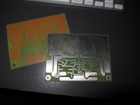
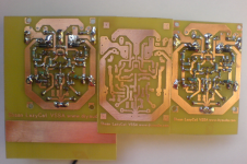
Here's my first two TO3 PeeCeeBee's. Will begin to populate them with parts on hand very soon.
Great job!
I'd love to see working amp and those robust TO-3 animals onboard. Also you'll be the one to have the opportunity to compare it with ALF-s.
Happy assembly.

 , unit that is essentially my junk box special. If it sings I'll get superior components for the project.
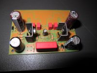
Hello
I have made 2 peeceebee boards and have small problem with one channel.
I am getting not symetrical gnd to mosfets gate voltages and offset is growing from 1mV (cold) to 13mV (hot).
Is the vas current ok in my board, leave it as it is?
The other board is fine (bias 110mA, symetrical from in to out all currents, vas is 25mA)
BIG thanks
Sorry forgotten - supply is +-37V
Attachments

Last edited:
hi,LC can i use irfp240/9240 insted 2sk1058/2sj162?
I do not know if you can use it but I know that if you are going to use it you should add some bias compensation (additional transistor mountet on heatsing with outputs). Looks like pair irfp240/9140 suits better.
nice borys!...how does it sounds?
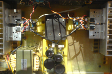
First impression is nice, but I have listen only free air full range driver so can not say much about it. There is hearable noise when I put my ear to the speaker, from the distace is dead silent.
I have 20cm not shielded wires to the input and there is loud noise comming from speaker if I leave in not connected to gnd - so input has to be well shielded.
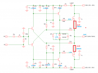
Input low pass filter essentials:
- 100 pF capacitor from bases to GND located as close as possible to input transistor pair
- signal serial resistor value at least 560 Ohm
- input interconnect cable can be unshielded, but in this case should be anti-parallel to speaker cable and located away from it, to avoid their coupling, otherwise one can get HF positive feedback and consequently amp's oscillation. This cannot happen with shielded input interconnect cable. Tested.
Also no sound of the VSSA can be evaluated before min 50 hours of burn-in period, since elcos in FB path changes the sound signature from hour to hour since it stabilizes to normal conditions. Also tested.
Thanks very much for advise!
Can you tell me can I leave vas bias as it is 25mA(after 30min stabilise) ?
In atatchment I have measurement. THX
Attachments
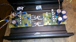
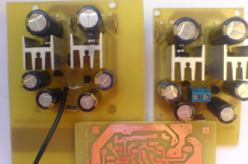
Hi,here is another PCB.I tried CCS circuit (jfet 2sk170 and two resistors) instead of one resistor.It can be easily inserted in pecebe as a module or P2P leg to leg,but i went another way,new SMD-melf based pcb.Ok it's messy as it's one sided.Had to use some laquie to be 99% sure it is safe.
Farnell forgot to include 22pf (compensation) capacitors in my order,so at first ,without them amp was oscillating - one amps both chanells had strange hum,another amp in the background had sound like CDP trying to play scratched CD but after i found some 10pf everything went fine.
Used j112 in CCS.
Also 1K feedback resistors instead of shaan's 2.2K-didnt measured active speakers setup yet,but the gain was changed i think this way...
The sound with shaans pcb and CCS was like heaven,now-i can't say so.All new capacitors needs time,so do i,i finished it only few hours ago..
Farnell forgot to include 22pf (compensation) capacitors in my order,so at first ,without them amp was oscillating - one amps both chanells had strange hum,another amp in the background had sound like CDP trying to play scratched CD
but after i found some 10pf everything went fine.Used j112 in CCS.
Also 1K feedback resistors instead of shaan's 2.2K-didnt measured active speakers setup yet,but the gain was changed i think this way...
The sound with shaans pcb and CCS was like heaven,now-i can't say so.All new capacitors needs time,so do i,i finished it only few hours ago..
Attachments
Last edited:
You're welcome.Thanks very much for advise!
Can you tell me can I leave vas bias as it is 25mA(after 30min stabilise) ?
In atatchment I have measurement. THX
VAS bias should be 12-15 mA, just in a middle of hFE/Ic curve where VAS BJTs are in the most linear region. Also 25 mA gives senseless too much heat to dissipate. Adjust both 15k resistors to set correct VAS bias and 0 mV output DC offset.
The sound with shaans pcb and CCS was like heaven,now-i can't say so.All new capacitors needs time,so do i,i finished it only few hours ago..
Congratulations!
Happy listening.
- Home
- Amplifiers
- Solid State
- PeeCeeBee