More than three decades after they were released the NE5532/5534 opamps
are still the most used in high perfs audio items , it s not by chance
and i like to add an original NE5534 based low power amp that will show
that this op amp potential is not fully exhausted.
As in many opamps there are two pins dedicated to an external compensation
but there s a convenience with the 5534 since thoses pins are connected
to the VAS input and output , the output stage being not included in the
external compensation loop.
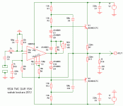
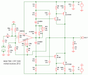
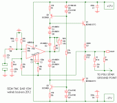
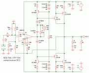
This allow to implement a TMC compensation scheme that will include
both the 5534 output stage and an attached power output stage consisting
of either darlington or eventualy CFP or lateral fets.
The improvement in linearity compared with the same circuit with only
local compensation is quite amazing , distorsion is drasticaly
reduced but the most advantageous is quasi anihilation of crossover
distorsion that shouldnt be audible even if the output stage is biaised
with only a few mA.
Personnaly i use a pair of Sanken darlingtons as output stage but
since there are members that are fond for other output stage topologies
i simulated versions with lateral fets and CFP output stages wich seems
to work as well as the darlingtons and even with slightly lower THD
for the CFP.
12W/8R might not be impressive but it s more than enough for home listening
provided the speakers are not half mute with catastrophic SPL/watt , and the
perfs are as good if not better than what can be extracted from expensive
dedicated drivers.
are still the most used in high perfs audio items , it s not by chance
and i like to add an original NE5534 based low power amp that will show
that this op amp potential is not fully exhausted.
As in many opamps there are two pins dedicated to an external compensation
but there s a convenience with the 5534 since thoses pins are connected
to the VAS input and output , the output stage being not included in the
external compensation loop.
This allow to implement a TMC compensation scheme that will include
both the 5534 output stage and an attached power output stage consisting
of either darlington or eventualy CFP or lateral fets.
The improvement in linearity compared with the same circuit with only
local compensation is quite amazing , distorsion is drasticaly
reduced but the most advantageous is quasi anihilation of crossover
distorsion that shouldnt be audible even if the output stage is biaised
with only a few mA.
Personnaly i use a pair of Sanken darlingtons as output stage but
since there are members that are fond for other output stage topologies
i simulated versions with lateral fets and CFP output stages wich seems
to work as well as the darlingtons and even with slightly lower THD
for the CFP.
12W/8R might not be impressive but it s more than enough for home listening
provided the speakers are not half mute with catastrophic SPL/watt , and the
perfs are as good if not better than what can be extracted from expensive
dedicated drivers.
Attachments
12W/8R might not be impressive but it s more than enough for home listening
provided the speakers are not half mute with catastrophic SPL/watt , and the
perfs are as good if not better than what can be extracted from expensive
dedicated drivers.
Hi Wahab
very, very nice!
")
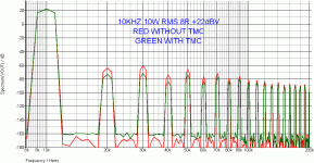
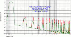
Hi Dadod , i ll have to re do the sims and post a few results ,
here the THD improvement at 1 and 10Khz , this is with
darlingtons and bootstrap , the simplest version above ,
iddle current being about 65mA.
here the THD improvement at 1 and 10Khz , this is with
darlingtons and bootstrap , the simplest version above ,
iddle current being about 65mA.
Attachments
Hi Dadod , i ll have to re do the sims and post a few results ,
here the THD improvement at 1 and 10Khz , this is with
darlingtons and bootstrap , the simplest version above ,
iddle current being about 65mA.
Wahab I expected higher improvemnt with a TMC at 10kHz then at 1kHz.
The improvement at 1KHZ is better because the transition
frequency of the TMC network is set very low , typicaly
at 160Khz in this circuit and this is set wit R8 wich
consequently has higher value than what can be seen
in others schematics that use this compensation.
Dramaticaly higher improvement at higher frequencies
is possible by increasing the transition frequency/reducing
the resistor to a couple KR but this will be at the expense
of stability under capacitive loadings so i elected for this
cautious value , THD10Khz residuals being below -92db.
Hi Dadod , i ll have to re do the sims and post a few results ,
here the THD improvement at 1 and 10Khz , this is with
darlingtons and bootstrap , the simplest version above ,
iddle current being about 65mA.
What model are you using for the 5534? The only free model that I have seen is originating from TI and is a particular implementation of the Boyle macromodel. In the Boyle macromodel, only the input differential pair is modelled using bjt's, everything else is VCCS's and fixed I/V sources. While Boyle macromodels can be more or less successfully used to model small signal AC behaviour (like modelling the loop stability), for large signal modelling (like distortion analysis), they are completely useless (at least because the VAS, being modelled as an ideal VCCS, has always 0 (zero) distortions). Device level op amp models are rare, one of the best known is the LME49710. Therefore, in general, distortion modelling of op amp based circuits is an useless exercise.
The delta between the standard and the TMC versions is due to the transitioning from Miller compensation to a two pole type compensation, having a theoretical and ideal advantage of 6dB more global feedback, hence less distortions. Unfortunately, implementing a two pole compensation schema with the 5534 is less than optimal, because the internal Miller compensation (between the same two pins) can't be disabled, hence a smaller than expected delta.
There's nothing special about the 5534 in such applications, other than having the two pins (comp and comp/bal) available (which is, BTW, a characteristic of first generation op amps, not many modern op amps have the same feature - because op amps are today much more specialized components than they used to be).
The VAS modelisation need not to include its non linearity since
most of it comes from the output power stage anyway.
I m aware of the 5534 internal compensations and particularly the 12pF
miller cap you re pointing.
Neverless , it should work well enough , i ll do some real world measurements
once i ve got the 5534s to accurately set the external compensation on the bench.
The VAS modelisation need not to include its non linearity since most of it comes from the output power stage anyway.
It's not only about the VAS linearity, but also about the VAS output impedance, which is not correctly modelled in the Boyd macromodels. The output stage (non) linearity (other than crossover distortion) depends essentially on the VAS output impedance (the lower the better).
- Status
- This old topic is closed. If you want to reopen this topic, contact a moderator using the "Report Post" button.
- Home
- Amplifiers
- Solid State
- 5534 TMCed low power amp