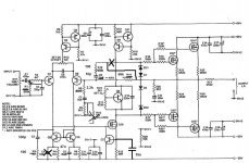
This blasphemy, probably, but I was not satisfied with the sound of the JLH 80W MOSFET amp, something was wrong. That was long time ago, and when finally I've got an oscilloscope I noticed small oscilations sometimes, and I did not like to high gain and to high value resistors used in the NFB, so I modified it.( http://www.diyaudio.com/forums/soli...power-amplifier-modifying-11.html#post2794339 ).
It is not anythig close to MIC anymore, but I like it better now. I used different small MOSFET as I don't have VN1210 model, used BSS123, so it could be some differnces there.
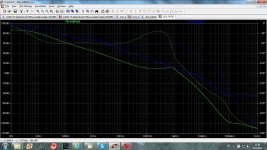
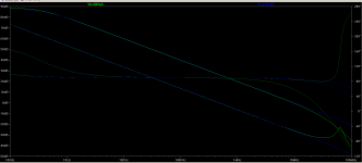
LG picture, green original JLH, blue modified.
Damir
It is not anythig close to MIC anymore, but I like it better now. I used different small MOSFET as I don't have VN1210 model, used BSS123, so it could be some differnces there.
LG picture, green original JLH, blue modified.
Damir
Attachments
Ed Cherry also in 1982, although briefly (what I've quoted in post 723 is all of it AFAIR).
Hi Steve,
Thanks for this additional reference to MIC. Ed Cherry was prolific in his writing at the time and I am not surprized if he touched on what we are now calling MIC.
Cheers,
Bob
This has always been JLH's favourite method of compensation.
I've just checked that he doesn't compensate his 1969 Class A amp at all. But he certainly discusses it in his 1975 HiFi News 75W amplifier series.
_______________
Bob I think it may be worth discussing the need for zillion V/us slew. A 100W@8R amp gives V = 40 exp(jwt) Volts at max power.
The slew rate for this is dV/dt = j w 40 exp(jwt)
If the amp has a first order roll-off at f3dB, then the maximum slew rate the amplifier needs is twice that for a rail to rail sinewave at f3dB. You get this for an unclipped square wave whose rise time will reflect the bandwidth of the amplifier.
Any other roll-off will require less slew rate until when you have a brickwall filter (eg Red Book CD) the requirement is the same as for a a rail to rail sinewave at f3dB.
This means that you'd only see zillion V/us slew when the amp is severely overloaded. Beyond a certainly level, the slew only reflects the linear bandwidth of the amp.
Overload recovery and the lack of nasty artifacts are usually more important than high slew when coming out of overload.
In fact, one could argue that slew rate should be deliberately limited to what's required for low THD on a rail to rail sinewave at 2 x f3dB. The harmonics on overload would be more 'benign' cos the result would be a truncated triangle wave instead of a square wave.
_____________________
On much surer psychoacoustic ground is deliberate bandwidth limiting. I don't think there is any need for a power amp to have a 3dB bandwidth exceeding 100kHz. Some parties, eg the Broadcast Organisations, in fact insist on much lower bandwidths.
ALL the reliable blind listening tests on band limiting of electronic signals, both this and the previous millenium, show a clear preference for the band limited signal from those who can reliably tell the difference.
Our 100W 8R, 100kHz amplifier only needs a slew rate of
2 x 40 x 2 x pi x 100,000 = 50.26 V/us
This is halved if its 3dB bandwidth is 50kHz and reduced by nearly 10x if it is only playing Red Book CD.
Hi kgrle,
You are right about the matter of how much slew rate is really needed in an amplifier. A long long time ago I wrote an article in Audio called "Another View of TIM" (I think I have it on my web page at CordellAudio.com - Home). In that article I touched on the slew rates of various sources and followed much of the logic that you presented here. At the time TIM was the rage, and I got hammered for putting the need for slew rate into numerical context.
It is certainly true that most sources don't produce great amounts of slew rate. For example, a 20kHz sinewave produces about 0.125 V/us per volt peak of the signal. However, Amplifiers with higher slew rate usually have a lot more margin against HF nonlinearity, so in comes the valid matter of what was then called soft TIM. Bottom line is that I usually like to see an amplifier have at least 10X the slew rate needed for it to do full power on a 20kHz sinusoid.
What really counts is HF linearity in the open and closed loop.
I agree, the 300V/us of my 1983 50-watt amplifier was way more than needed, but achieving that high slew rate was not a primary goal of the design. It just turned out that way because of my use of Miller Input Compensation.
Cheers,
Bob
If I remember corrrectly, J. L. Hood used 220p MIC on his MOSFET designs. I am not certain he degenerated his input stage though.
I've just checked the few JLH articles I have. The MIC components were:
- 1982: 5pF + 47k; cf 33k feedback resistor
- 1989: 10pF; cf 56k feedback resistor
- 1993: 5pF + 120k; cf 39k feedback resistor
Perhaps the 220pF was only very early on in his writings, or you have misremembered?
I have regularly noticed that this is a favorite of most of the 70's into 80's British designers.This has always been JLH's favourite method of compensation.................
Would I be correct to surmise they were talking to each other?
It is certainly true that most sources don't produce great amounts of slew rate. For example, a 20kHz sinewave produces about 0.125 V/us per volt peak of the signal. However, Amplifiers with higher slew rate usually have a lot more margin against HF nonlinearity, so in comes the valid matter of what was then called soft TIM. Bottom line is that I usually like to see an amplifier have at least 10X the slew rate needed for it to do full power on a 20kHz sinusoid.
That would be the small signal slew rate, which is tied to the frequency corner where the closed-loop gain meets the amplifier open-loop gain curve. The small signal slew rate is usually discussed in terms of "rise time" and the well known expression Tr=0.35*Acl/Fu where Acl is the closed loop gain and Fu is the amplifier ULGF.
This being said, your requirement of a 10x the slew rate to do the full power on a 20KHz sinusoid is in fact a requirement for the amp ULGF: SR=Vout/Tr=Vout*Fu/(0.35*Acl)=Vin*Fu/0.35 => Fu=0.35*SR/Vin. Which, in all truth, I don't think it makes much sense, and here is why:
The full power on a Fo=20KHz sinusoid is achieved at a slew rate of 2*PI*Vout-peak*F=2*PI*SQRT(2)*Vout*F. If you want the amp to have a k times more slew rate than at Fo, then this maps to (see above, 0.35 is 2.19/(2*PI) where 2.19 comes from the 10-90% SR limits) k*2*PI*SQRT(2)*Vout*Fo=Vout*Fu/(0.35*Acl) => k*SQRT(2)*Fo=Fu*Acl/2.19. This is in fact a condition for the amp ULGF, Fu=k*SQRT(2)*2.19*Acl*Fo. Putting in some numbers, k=10 as you said, Acl=26dB (x20), Fo=20KHz we get Fu=12.35MHz. You would of course agree that this is way larger than practically achievable in an audio amp.
Now, maybe you are talking about a constraint for the large signal slew rate, as an effect of the input stage nonlinearities? That would be a different story, the large signal slew rate (what is actually called "slew rate" in most data sheets) has little to nothing to do with the small signal slew rate. I would fully agree that a large signal slew rate of 10x the slew rate required to do the full power bandwidth at 20KHz makes sense, and that would be (again see above) k*Fu/(0.35*Acl) for each volt at the output, which leads immediately to an amp SR requirements (for the same Acl=26dB, k=10 and taking Fu=1MHz) of 1.42V/uS for each volt at the output. This is a good and perfectly achievable value, significantly larger than the old rule of thumb of 0.5V/uS for each output volt.
In at least one article he suggested the resistor be "tuned" for best squarewave shape, using a pot wired as rheostat.I've just checked the few JLH articles I have. The MIC components were:
- 1982: 5pF + 47k; cf 33k feedback resistor
- 1989: 10pF; cf 56k feedback resistor
- 1993: 5pF + 120k; cf 39k feedback resistor
Perhaps the 220pF was only very early on in his writings, or you have misremembered?
This implied that different builds would require a different R even though all were supposed to be using the same PCB and the same components.
It seems clear that he recognised that the stability margin does vary with device parameters.
Other than increasing slew rate MIC has no practical value
linearity wise , a moderate TMC yield lower distorsion even
at the upper side of the audio spectrum.
TMC could be used as MIC(TMIC ?), but again if to get same phase margin and gain margin it should be internaly compensated and we are back to similar distortion as ordinary TMC.
I'm sure y'all are aware of the A40 (40 watts class A) amplifier that Nelson Pass published in Audio Amateur (1978). Here is the full article and the circuit schematic is below. Please note frequency compensation capacitor C4.
Attachments
JLH used 5pF in series with 470k resistor in his 80W MOSFET amp, but he used RC network too, C3, R3.
Damir
Does it still work the same as MIC? With R10 > R14, the series impedance of the MIC compensation components is never <= the global feedback resistance.
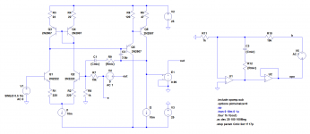
I've done some sims of the global loop for resistors in series with the MIC capacitor - schematics and results attached. The two circuits are a basic three-stage amplifier with discrete components and an amplifier built with ideal opamps. In both cases, the ULGF without MIC is ~10MHz. I included the opamps as I've seen Walt Jung use MIC with them a number of times.
The first set of results shows the global loop gain without MIC (upper traces); and the global loop gain with the ULGF aimed at 500kHz by the 17pF MIC capacitor and the 19k feedback resistor (lower traces). Green lines are the discrete circuit and blue are for the opamps. They show MIC working as predicted.
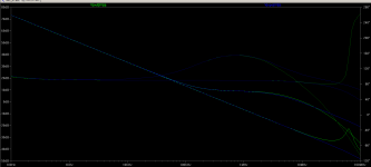
The second set of results has the MIC resistor set to three times the feedback resistor similar to the JLH circuit that dadod posted. It appears that MIC doesn't adequately compensate the global loop on its own in this case, as the loop gain plateaus at ~9dB before falling to unity at the original 10MHz.
My gut feel is that making the MIC resistor 1/3 of the feedback resistor would be good but needs more simulation which will have to wait.
Attachments
Last edited:
The 220p and discussion was in his 1972 HiFi News 75W amplifier article. I may have the instructions for the Powertran kit which has a full reprint but it might be difficult for this beach bum to find.I've just checked the few JLH articles I have. The MIC components were:
- 1982: 5pF + 47k; cf 33k feedback resistor
- 1989: 10pF; cf 56k feedback resistor
- 1993: 5pF + 120k; cf 39k feedback resistor
Perhaps the 220pF was only very early on in his writings, or you have misremembered?
He has the circuit in his "Valve and Transistor Audio Amplifiers" book.
http://books.google.com.au/books?id...r_esc=y#v=onepage&q=jlh 75w amplifier&f=false
Its fig 8.12 on pg 154 if you can persuade google books to show it.
Mea maxima culpa for my misleading 1975 reference.
Not so... the large signal slew rate (what is actually called "slew rate" in most data sheets) has little to nothing to do with the small signal slew rate.
The 'large signal slew' has to be large enough to support the 'small signal slew' if the amplifier is to remain linear. The 'small signal slew' or rise time is directly related to the -3dB bandwidth (and also whether its 1st order roll-offs bla bla)
eg a 100W @ 8R amp with 300V/us would need to be bandlimited to 100kHz x 300/50.26 = 596.9kHz. (from my 100W amp example)
Otherwise it would slew rate limit on a fast rail to rail square wave. If you have less bandwidth, the amp would overload before it slew limited. That's assuming you don't really want rail to rail sine waves at 2MHz.
")
You may like to sim. this with some 'perfect' amps with the same bandwidths and rails.
___________________
Bob, I like to achieve supa dupa numbers like 1pp zillion THD and zillion V/us slew too.
But I would only do that if it could be done without extra bits. (I'm old fashioned in that respect and have been known to call up young engineers when their new design has more bits than what they replace. But really, as a speaker man, I'm far more interested in how nice an amp is to my evil speaker loads under ALL conditions.
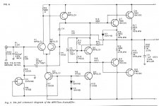
The 220p and discussion was in his 1972 HiFi News 75W amplifier article... He has the circuit in his "Valve and Transistor Audio Amplifiers" book. Its fig 8.12 on pg 154 if you can persuade google books to show it.
It's shown as 220uF in that book, but I have another version of the schematic that confirms 220pF was the value (I thought maybe 22p was intended but misprinted as 220).
The feedback resistor is 22k in that design giving ~30kHz ULGF for the global loop. JLH says the design was good for 0.01% THD at 75W/8R (frequency not stated). Is that realistic for a class AB quasi-complementary output stage with bugger all feedback around it? Perhaps I'm missing something in the details...
In relation to your slew rate/band limiting musings, JLH's 1982 amplifier has a 4k7/1nF input lowpass filter for 34kHz.
Other than increasing slew rate MIC has no practical value
linearity wise , a moderate TMC yield lower distorsion even
at the upper side of the audio spectrum.
Hi wahab,
In most cases, if I had to choose between MIC and TMC for an amplifier, I would choose TMC, since it gives more bang for the buck where it is needed most - reduction of distortion in the output stage. Output stage crossover distortion, for example, is much more insidious than the typically softer mostly third-order distortion from an LTP input stage (as long as the amplifier is not in slew rate limiting).
I used MIC in my MOSFET amplifier with error correction because I already had dealt with the output stage distortion with the use of error correction. In that situation, the MIC helped achieve high slew rate and very low input stage distortion. I also was quite frankly unaware of TMC at the time.
In the absence of TMC, MIC does have value linearity-wise beyond increasing slew rate. That, of course is the linearity of the input stage. Linearity of the input stage is important insofar as what used to be called "soft TIM". In some cases, the added linearity provided by MIC might also allow a smaller amount of input stage degeneration to be used, if desired.
Cheers,
Bob
The 'large signal slew' has to be large enough to support the 'small signal slew' if the amplifier is to remain linear. The 'small signal slew' or rise time is directly related to the -3dB bandwidth (and also whether its 1st order roll-offs bla bla)
eg a 100W @ 8R amp with 300V/us would need to be bandlimited to 100kHz x 300/50.26 = 596.9kHz. (from my 100W amp example)
Otherwise it would slew rate limit on a fast rail to rail square wave. If you have less bandwidth, the amp would overload before it slew limited. That's assuming you don't really want rail to rail sine waves at 2MHz.
Not sure I follow. The small signal slew rate may be (and usually is) far below the large-signal value. A common opamp as the TL071 is specified with a (large signal) slew rate of 13V/uS. The rise time is specified at 100nS/20mV step, so the small signal slew rate is not more than 0.16V/uS. If you compare the rise times (or the small signal slew rates) for two different opamps, you'll note that the small signal slew rates are in the same ratio as the gain-bandwidth products.
Perhaps I'm missing something, but your example of limiting the bandwidth for high (large signal) slew rates amplifiers doesn't make any sense. A input low pass filter set at a few 100's of KHz has a completely different role of filtering the ingress RF. If your amp doesn't fully behave with fast input transients, without the input LP filter, then you have a global or local stability issue and the design has to be revisited.
TMC is not comparable to single pole compensation - it is 2-pole
thats a faulty comparison - TMC is a "2-pole" compensation – TMC should be compared with other 2-pole schemes – TMC requires the same level of knowledge, skill to safely apply as other 2-pole compensations
2-pole could be done with “MIC” and then the "extra" loop gain that could be equivalent to some tuning of TMC would be available to the entire amplifier, input and output - just like the conventional Miller position TPC
I am afraid the "single pole" appearance of the global loop with TMC is deceptive - leads people to think TMC is "trivial" - to think incorrectly that TMC stability is some how better than other 2-pole schemes, that it is fine to recommend to less sophisticated builders without the inclination or skill to use other 2-pole schemes
we apparently need to keep repeating the warning that TMC is 2-pole
In most cases, if I had to choose between MIC and TMC for an amplifier, I would choose TMC
thats a faulty comparison - TMC is a "2-pole" compensation – TMC should be compared with other 2-pole schemes – TMC requires the same level of knowledge, skill to safely apply as other 2-pole compensations
2-pole could be done with “MIC” and then the "extra" loop gain that could be equivalent to some tuning of TMC would be available to the entire amplifier, input and output - just like the conventional Miller position TPC
I am afraid the "single pole" appearance of the global loop with TMC is deceptive - leads people to think TMC is "trivial" - to think incorrectly that TMC stability is some how better than other 2-pole schemes, that it is fine to recommend to less sophisticated builders without the inclination or skill to use other 2-pole schemes
we apparently need to keep repeating the warning that TMC is 2-pole
Last edited:
Perhaps I'm missing something, but your example of limiting the bandwidth for high (large signal) slew rates amplifiers doesn't make any sense. A input low pass filter set at a few 100's of KHz has a completely different role of filtering the ingress RF. If your amp doesn't fully behave with fast input transients, without the input LP filter, then you have a global or local stability issue and the design has to be revisited.
the TMC/TPC debate brings to the front the issue of amplifier step response interpretation, significance
we are used to single dominant pole compensated amps where overshoot, ringing are 1st order related to stability margins
this is not the case generally - control theory regularly separates system response design from feedback loop frequency/step response with added prefilters - this can allow different and possibly better performance in some feedback controlled characteristics while meeting system frequency response requirements
we apparently need to keep repeating the warning that TMC is 2-pole
Unbelievable. After hundreds of messages and threads discussing this, it still doesn't get through. TMC appears to be one of the most deceptive ideas I've seen in audio.
What also doesn't go through is that for a minimum phase system (as usual in audio, not much use of all pass filters) the maximum loop gain is a function of ULGF and the loop gain order. That's it, no way around, no free lunches, everything else comes to a stability margin price.
- Status
- This old topic is closed. If you want to reopen this topic, contact a moderator using the "Report Post" button.
- Home
- Amplifiers
- Solid State
- Audio Power Amplifier Design book- Douglas Self wants your opinions