Douglas,
You really would think that if an invention had a commercial application you would want the patent to be found so that it would not be infringed upon. The cost to protect or attempt to disqualify a patent is expensive and obfuscation seems silly on the face or it, unless of course you are a patent lawyer and then job security could be an end result!
You really would think that if an invention had a commercial application you would want the patent to be found so that it would not be infringed upon. The cost to protect or attempt to disqualify a patent is expensive and obfuscation seems silly on the face or it, unless of course you are a patent lawyer and then job security could be an end result!
It has been pointed out several times now that so far as anyone knows, the original inventor was Kunio Seki, in 1978; see US Patent 4,145,666 assigned to Hitachi. Unlike some people, I have never at any point claimed I invented it, re-invented it, popularised it, or done anything with it except use the information passed on to me by Peter Baxandall. I may however be the only person in this discussion who has actually made money out of it.
_____
I was not quibbling about who invented that which we now know as TMC, nor was I suggesting you claimed to invent it. It is indeed a shame that the Hitachi circuit went essentially unknown for such a long time. I only learned about it from Edmond, here. I wish I had known about it decades ago. I said that you were late to the party because you apparently did not involve yourself with it until after the detailed discussions that took place here quite awhile back. Indeed, in five editions of your book you never mentioned this technique that you subsequently described as so powerful in the Linear Audio article you wrote in late 2010. I'm guessing that if Edmond had not brought it up here, to this day you would not be touting its value. Ditto for me.
___
In your 600 page book, you only referenced my work five times.
I should have mentioned you in Chapter 3, where I evolved the old simple standard-bearing amplifier circuit with obvious engineering refinements into largely that which you call Blameless. That basic amplifier and its straightforward refinements has been around pretty much since the dawn of silicon transistors, but you poineered the systematic dissection of its sources of distortion. I just described its evolution with a different style so I could help those less experienced understand the circuit design techniques and use that basic amplifier as a launching pad for more sophisticated amplifiers. I think that one of your most important contributions is in the understanding of output stage static crossover distortion, and in chapter 10 on output stages I referenced you numerous times, and those references were well deserved.
______________
(For those not in the know, this diagram shows the very large currents that can be drawn by a loudspeaker if you hit it with a carefully designed set of pulses)
I gather that you published your version in 1983. I am not aware of this publication; perhaps you could enlighten us.
My diagram was directly inspired by the well-known but fallacious paper by Otala et al: "Peak Current Requirement of Commercial Loudspeaker Systems" JAES Volume 35 Issue 6 pp455-462; June 1987. It is of course of little more than curiosity value as the irregular square waves that are required to show the effect do not exist in music.
My diagram first appeared in the very collectable Second edition of Audio Power Amplifier Design, in 2000. That is a long time to harbouri a grievance.
______
I don't understand how you could be unaware of that diagram or my paper in which it was published. You reference that very same paper in that same chapter at a later point (my paper on Interface Intermodulation Distortion). I own fully 3 editions of your excellent book, but not editions 2 and 3. I hope you will reference it properly in your sixth edition.
Cheers,
Bob
Doug, may I ask if these cb capacitors on the drivers were on an amp where the output devices were connected via twisted leads rather than soldered directly to the PCB?The shunt capacitors have been found to be effective with both an EF-VAS (with added emitter-follower) and a bootstrapped cascode VAS, in large quantity production over many years.
My contention is that if the layout is rigorously controlled, including the connections to the outputs, (no long evil twisted leads) it is possible to do without them.
Very considerate, Edmond. But why would anybody expect anything better from you?
True!

Then again Edmond has always been a bit of an ***.
We need to simplify as much as possible .. not add complexity which will make things further from real life .. especially if good practice can get rid of certain evils.
Not at all. This is exactly what I'm trying to simulate.Are we on cross purposes here? I only made this suggestion in oder to find out why some implementations of Cherry's amp were unstable.
My contention is that for output devices on sensible PCB layouts without evil 6" connections, the 33p collector/base caps on the devices that Cherry uses are redundant .. as are heretical variations of pure Cherry like TMC
Of course as a beach bum, relying on experience from more than 2 decades ago, I'm on very shaky ground in this august company.
On the subject on evil twisted 6" leads, isn't there a fair amount of coupling capacitance in addition to the inductance, mutual and otherwise of the leads.
I fully understand that DIY stuff may require evil twisted or ribbon 6" leads but I feel a commercial design should have the PCB fully define any paths .. and hence remove the need for 33p collector/base caps on drivers or even TMC.
EF vs CFP
If I may return to the original thread ..
In Figs 5.39 & 5.40 of the 4th edition, Doug shows what happens at low power between EFII and CFP. He shows that CFP output stages may exhibit the evils of crossover distortion to a greater extent.
This is certainly worth further real life investigation. I've seen some evidence of this myself, but 20+ yrs ago, I couldn't measure THD to that precision at those levels.
AmenIf I may return to the original thread ..
In Figs 5.39 & 5.40 of the 4th edition, Doug shows what happens at low power between EFII and CFP. He shows that CFP output stages may exhibit the evils of crossover distortion to a greater extent.
This is certainly worth further real life investigation. I've seen some evidence of this myself...
This is my impression also.
Can someone reference the pics to the 5th edition?
Best wishes
David
Not at all. This is exactly what I'm trying to simulate.
My contention is that for output devices on sensible PCB layouts without evil 6" connections, the 33p collector/base caps on the devices that Cherry uses are redundant .. as are heretical variations of pure Cherry like TMC
Of course as a beach bum, relying on experience from more than 2 decades ago, I'm on very shaky ground in this august company.
On the subject on evil twisted 6" leads, isn't there a fair amount of coupling capacitance in addition to the inductance, mutual and otherwise of the leads.
I believe that, compared to the capacitances of the O/P devices itself, the coupling capacitance between the leads is of little influence. Cbe is a few nF!
I fully understand that DIY stuff may require evil twisted or ribbon 6" leads but I feel a commercial design should have the PCB fully define any paths .. and hence remove the need for 33p collector/base caps on drivers or even TMC.
Short story: If you omit the 33p caps, things get much more complicated.
Long story: In case of Miller output inclusive compensation (MOC), we are dealing with a (relative) high output impedance of the TIS. Tied to the drivers, which also exhibit a high (input) impedance, the resulting impedance is high too. The overall gain as well as the Miller loop gain strongly depends on this (the higher the impedance, the higher the gain). But we have little control over it, as it's defined by the parasitic capacitances of the trannies, Early effect, stray capacitance and stray inductance. IOW, it's a rather unpredictable and ill defined affair. At about 10MHz, being approximately the ULGF of the Miller loop, this means trouble. To get rid of this unpredictable behavior, just overrule the aforementioned impedance by a lower and better defined one. That are the two 33p caps for. Now you get (about) 6dB/oct roll-off and the Miller loop will be (more) stable.
That being the case, these caps are certainly not 'redundant'. Even which shortest possible leads to the O/P devices, I wouldn't omit these caps.
Cheers,
E.
If I may return to the original thread ..
In Figs 5.39 & 5.40 of the 4th edition, Doug shows what happens at low power between EFII and CFP. He shows that CFP output stages may exhibit the evils of crossover distortion to a greater extent.
This is certainly worth further real life investigation. I've seen some evidence of this myself, but 20+ yrs ago, I couldn't measure THD to that precision at those levels.
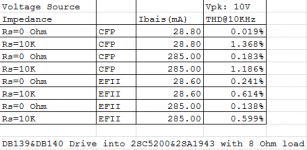
As my experience.
If you use TMC compensation. EFII is more linear.
If you use normal miller compensation. CFP is more linear.
Why?
Because CFP has strong local voltage negative feedback to ensure high linearity when it is driven by voltage source.
On contrast, EFII has high linearity when it is driven by current source.
When you use TMC compensation, most of time(Low Freq.) the output stage is included in miller compensation. Then you can look VAS as a current source. EFII is more suitable for this job.
When you use normal miller compensation, the strong local nagetive feedback on VAS make it more like a voltage source. CFP does well in this case.
Last edited:
If I may return to the original thread ..
In Figs 5.39 & 5.40 of the 4th edition, Doug shows what happens at low power between EFII and CFP. He shows that CFP output stages may exhibit the evils of crossover distortion to a greater extent.
This is certainly worth further real life investigation. I've seen some evidence of this myself, but 20+ yrs ago, I couldn't measure THD to that precision at those levels.
I believe this is true, and is one of the reasons I do not recommend the use of CFP output stages, as explained in chapter 5 (5.4) of my book.
Cheers,
Bob
As my experience.
If you use TMC compensation. EFII is more linear.
If you use normal miller compensation. CFP is more linear.
Why?
Because CFP has strong local voltage negative feedback to ensure high linearity when it is driven by voltage source.
On contrast, EFII has high linearity when it is driven by current source.
When you use TMC compensation, most of time(Low Freq.) the output stage is included in miller compensation. Then you can look VAS as a current source. EFII is more suitable for this job.
When you use normal miller compensation, the strong local nagetive feedback on VAS make it more like a voltage source. CFP does well in this case.
This is a very interesting observation as to whether the output stage is effectively voltage driven or current driven depending on whether the compensation is conventional Miller or TMC. The effective driving mode may also depend on the effective input impedance of the output stage, depending on whether it is a Double or a Triple.
In any case, I usually think of the output stage as being voltage driven as my starting baseline is conventional Miller compensation and the use of a Triple output stage.
If a double-EF output stage and a CFP output stage are both being voltage-driven, I still believe that the CFP is more prone to distortion due to its typically much-higher transconductance at a given bias current, making optimum idle bias often lower and somewhat tricky (you may notice that some of the CFP output stages Doug shows must be somewhat starved of idle bias to achieve the optimum crossover relationship). A lower idle bias results in a smaller quasi Class A region where both halves of the output stage are contributing significant transconductance. This can result in higher distortion at small signal levels.
(BTW, MOSFETs, with their lower transconductance, like a higher idle bias, resulting in a larger "class A" region and often better sound).
One thing about the CFP output stage that many people overlook is the difference in linearity of a single CFP (good due to local feedback) versus that of a pair of CFPs hooked together in a class AB output stage (poor due to crossover distortion resulting from difficulty of splicing together two output sources, each of which has a low impedance). When voltage-driven, the CFP can be prone to serious gm doubling at reasonable idle bias operating conditions with reasonable values of RE equal to or greater than 0.15 ohm.
Finally, to the extent that we allow an output stage to operate in a current-driven regime, we now expose ourselves to much greater distortions resulting from beta mismatch and beta droop.
Cheers,
Bob
Hi, Bob,
It's nice to hear response from you.
You mentioned the driving mode might depend on the input impedance of output stage. That just let me remember something from your book and Douglas' book.
I have read both books, those are great books. I could have never built my first discrete amplifier without them.
The first difference I see between your design style and Douglas' style, is that you would use smaller value capacitor to do Miller Compensation comparing to Douglas' design. In most case, you would use 33pF, while Douglas prefers 100pF on VAS. The good thing is that smaller Cdom means larger slew rate, but on the other hand, it triples output impedance of VAS.
In some sense, the output of your VAS is more "current source like" than Douglas' VAS.
From that point of view, Douglas' VAS might be more CFP friendly. The same CFP might perform better on his platform than yours, since CFP deals with voltage source better than current source.
Another thing resulted by higher output impedance of VAS, is that it prefers higher input impedance of output stage to minimize the VAS load. In that case triple EF is a good choice.
I personally prefer EF instead of CFP. I just don't want to deal with parasitic oscillation in CFP without professional equipment.
Last edited:
This is a very interesting observation as to whether the output stage is effectively voltage driven or current driven depending on whether the compensation is conventional Miller or TMC. The effective driving mode may also depend on the effective input impedance of the output stage, depending on whether it is a Double or a Triple.
In any case, I usually think of the output stage as being voltage driven as my starting baseline is conventional Miller compensation and the use of a Triple output stage.
If a double-EF output stage and a CFP output stage are both being voltage-driven, I still believe that the CFP is more prone to distortion due to its typically much-higher transconductance at a given bias current, making optimum idle bias often lower and somewhat tricky (you may notice that some of the CFP output stages Doug shows must be somewhat starved of idle bias to achieve the optimum crossover relationship). A lower idle bias results in a smaller quasi Class A region where both halves of the output stage are contributing significant transconductance. This can result in higher distortion at small signal levels.
(BTW, MOSFETs, with their lower transconductance, like a higher idle bias, resulting in a larger "class A" region and often better sound).
One thing about the CFP output stage that many people overlook is the difference in linearity of a single CFP (good due to local feedback) versus that of a pair of CFPs hooked together in a class AB output stage (poor due to crossover distortion resulting from difficulty of splicing together two output sources, each of which has a low impedance). When voltage-driven, the CFP can be prone to serious gm doubling at reasonable idle bias operating conditions with reasonable values of RE equal to or greater than 0.15 ohm.
Finally, to the extent that we allow an output stage to operate in a current-driven regime, we now expose ourselves to much greater distortions resulting from beta mismatch and beta droop.
Cheers,
Bob
I just simulated some cases. You are right. CFP only works well when bias current is very small and the impedance of signal source must be low as well.
Attachments
Certainly. But the important cap is probably Cbc to which we add the evil 33pI believe that, compared to the capacitances of the O/P devices itself, the coupling capacitance between the leads is of little influence. Cbe is a few nF!
And the inductance is probably of greater importance than all of this. Anyone know why the evil leads are twisted? Apart from making things look neater?
Again this is certainly the case. However, my limited and Jurassic experience is that it is worth dealing with the problems cos you really need to do all that good layout stuff anyway for the best performance.Short story: If you omit the 33p caps, things get much more complicated. ... loadsa good stuff
If you sit down and work out the OL gains with 'voltage feed' vs 'current feed' at that point, you find that 'current feed' (keeping the VAS/output point at High Z) has LOADS more gain. At the same time, the distortions introduce by Beta mismatched/droop etc are always low order so the extra loop gain makes them disappear. That's assuming you are sufficiently versed in the art to avoid instability, local, parasitic, global .. uncle Tom Cobley ..
I believe Doug has said everything there is to be said about the evils of 'voltage drive' and how to minimize these .. including strict control of the bias point.
One of the advantages of pure Cherry is that the bias becomes quite non-critical and a 2:1 range still allows meeting a supa dupa THD@20kHz spec.
My prejudice is that the bastardized Cherry called TMC introduces 'some' evil voltage drive. A more practical point is that TMC and even TPC is another 2 components and this makes it difficult to introduce the PSR dodge I use in JFET 990 as C5.
If this sounds as though I'm anal about a couple of caps and resistors, that's cos I am
It's all about being anal about layout and how this might avoid extra evil 33ps etc._________
On the subject of strict control of bias, I hope Doug will expand on the thermal feedback mechanisms. Reading his 4th edition, I thought I had worked out a good strategy for myself but re-reading this, I find myself thoroughly confused again.
There's also the possibility of a little feedback circuit instead of the single bias transistor but again I suspect Doug would like to do a lot more real life work on this before pontificating further.
Certainly. But the important cap is probably Cbc to which we add the evil 33p
And the inductance is probably of greater importance than all of this.
I also think so.
Anyone know why the evil leads are twisted? Apart from making things look neater?
Because of less effective inductance (and radiation). The forward and return paths have opposite polarity. On a PCB I also would lay the traces to the emitters respectively collectors as close as possible together (or the one trace at the top side and the other one at the bottom side)
As for those two tiny caps, you really are 'anal' indeed.
, but I understand your motives. Cheer,
E.
Douglas,
You really would think that if an invention had a commercial application you would want the patent to be found so that it would not be infringed upon. The cost to protect or attempt to disqualify a patent is expensive and obfuscation seems silly on the face or it, unless of course you are a patent lawyer and then job security could be an end result!
That's not how it works. If you patent an idea but nobody notices, you have the best of both worlds. Your idea is still effectively secret, but if someone does come up with the same idea (and as we have seen here, that is not uncommon) then you can nail them. Protecting an idea from infringement is certainly expensive, but big companies are prepared to pay for it; look at Apple & Samsung, etc.
Douglas,
I think in certain ways we are starting to see a backlash against this type of action. Some companies have nothing but patent trolled, copied every perturbation of a name in-order to attempt to force a legitimate company to have to pay to recover their own brand identity. This type of action has been reversed in cases and I see that happening in other patent situations. Now big companies such as Apple and Samsung can afford to battle it out in court but that doesn't always help either side. Makes some lawyers very wealthy but can end in years long contest where both sides can damage their own public image. Oracle Corporation has found themselves in that position more than once at this point. The entire patent system is a mess at this time and changes will have to come, it doesn't seem to be sustainable the way the present system is working. One example is the Monsanto plant patents that is causing much consternation around the globe, they are being banned in entire countries due to predatory practices and questionable ethics.
I think in certain ways we are starting to see a backlash against this type of action. Some companies have nothing but patent trolled, copied every perturbation of a name in-order to attempt to force a legitimate company to have to pay to recover their own brand identity. This type of action has been reversed in cases and I see that happening in other patent situations. Now big companies such as Apple and Samsung can afford to battle it out in court but that doesn't always help either side. Makes some lawyers very wealthy but can end in years long contest where both sides can damage their own public image. Oracle Corporation has found themselves in that position more than once at this point. The entire patent system is a mess at this time and changes will have to come, it doesn't seem to be sustainable the way the present system is working. One example is the Monsanto plant patents that is causing much consternation around the globe, they are being banned in entire countries due to predatory practices and questionable ethics.
Douglas,
I think in certain ways we are starting to see a backlash against this type of action. Some companies have nothing but patent trolled, copied every perturbation of a name in-order to attempt to force a legitimate company to have to pay to recover their own brand identity. This type of action has been reversed in cases and I see that happening in other patent situations. Now big companies such as Apple and Samsung can afford to battle it out in court but that doesn't always help either side. Makes some lawyers very wealthy but can end in years long contest where both sides can damage their own public image. Oracle Corporation has found themselves in that position more than once at this point. The entire patent system is a mess at this time and changes will have to come, it doesn't seem to be sustainable the way the present system is working. One example is the Monsanto plant patents that is causing much consternation around the globe, they are being banned in entire countries due to predatory practices and questionable ethics.
And not only the patents but brand and name registration is in some way problematic. Here in Brazil, a big industrial group called Gradiente (nowadays is not so big and had few years ago financial problems) started near 2000 a registration, at brazilian patents office, of the name Iphone in Brazil.
The register was granted in 2008. There was no bad intentions on it because Gradiente was, at that time, a cell phone manufacturer.
Today Gradiente and Apple are talking about it, for sure it will cost some money to Apple.
- Status
- This old topic is closed. If you want to reopen this topic, contact a moderator using the "Report Post" button.
- Home
- Amplifiers
- Solid State
- Audio Power Amplifier Design book- Douglas Self wants your opinions