Fifth edition, page 129, figure 5.9, type 2 , the Lender-Boberly circuit seems to have something wrong in it.
Maybe the sixth edition could have some comments on Samuel Groner's comments on Audio Power Amplifier Design Handbook by Douglas Self. I was so fascinated by Samuel's circuit, page 48, figure 56 that I built it. I worked as intended on the bench, but I did not yet measured it
By the way, I have a blameless amp since1994, the boards were available through Electronics World, I think. It's still working fine.
Do you think you could be a bit more specific?Fifth edition, page 129, figure 5.9, type 2 , the Lender-Boberly circuit seems to have something wrong in it.
It has more than comments on it. Samuel Groner's document is an absolutely first-class bit of work, and we have worked together to extend many aspects of it. All is revealed in the sixth edition.Maybe the sixth edition could have some comments on Samuel Groner's comments on Audio Power Amplifier Design Handbook by Douglas Self.
Of course it is!By the way, I have a blameless amp since1994, the boards were available through Electronics World, I think. It's still working fine.
I think that it is wrong to reject and completely ignore CFA in your book....
.... CF amps simply sound much better than VF amps.
I absolutely do not accept this.
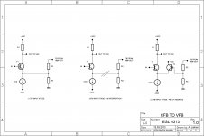
Let's call Tr4 the PNP emitter follower and Tr5 the NPN common emitter of the following stage which forms the VAS.Do you think you could be a bit more specific?
The role of the Vbe of Tr4 is to compensate for the Vbe of Tr5 in order to get the same voltage at the base of Tr4 and at the emitter of Tr5.
If we suppose the current passing through Tr5 to be 10 mA, it should be equal to the current trough Tr4, due to the current mirror effect.
Then the voltage at the emitter of Tr4 is to be around 10 V (1 kohm * 10 mA) + 0.6 V (voltage drop across the diode) + 1 V (voltage across the degenerating resistor of the current mirror).
Then the emitter voltage of Tr4 would be approximately equal to positive ouput rail minus 11.6V. The circuit is not going to work for usual power supply voltages of amplifiers.
I think that the right schematics should have a constant current source or a high value resistor loading the emitter of Tr4 and a constant current source loading the collector of Tr5. And that the 4k7 in the emitter circuit of Tr5 should be of a much lower value.
Last edited:
For a good balance in the input differential pair, voltage across each 4K7 should be equal, at around 2.35 V.
The configuration is dealt with very fully in the 6th edition, and input pair balance is a major theme.
Never said I could, if you are talking about slew-rate etc.
I do, and it has no downside. But wide bandwidth can easily be an embarrassment, leading to destructive oscillation. Some of the "fast" Japanese amplifiers were notorious for this.
I do. Nobody wants an amplifier that hums like a beehive.
But why? The implication is that you want a very fast slew-rate, but as I said upthread, what is really needed is the optimal slew-rate- faster than required for audio by ten times, say, for a good safety margin, but no more, so that if HF oscillation occurs we are not left cringing under a shower of molten silicon.
It's good to talk...
You've taken everything to the extreme to try to prove your point. So, no open discussion, just stubborn assertions.
In discounting CFA, you are ignoring an important class of amplifier and painting yourself in a corner on this one. There are many fine CFA commercial products (Acuphase, Krell for starters) . . . and DIYers will continue to build CFA designs (JLH's great 10W singleton CFA class A amp is still getting built and raved about 40 years on).
For my part, I'll continue designing and building both.
...So, no open discussion, just stubborn assertions...
On that topic, you never replied to this post.
Best wishes
David
To discuss with a Master does not make you a Master
Just show you are trying to be recognized as one...and proving you are not
Call Self stuborrn is an untolerable arrogance.
Unbeliavable people discussing with this man.
To be under the spot light may be the main need.... ridiculous all that stuff... answer his questions only.
Carlos
Just show you are trying to be recognized as one...and proving you are not
Call Self stuborrn is an untolerable arrogance.
Unbeliavable people discussing with this man.
To be under the spot light may be the main need.... ridiculous all that stuff... answer his questions only.
Carlos
Last edited:
(JLH's great 10W singleton CFA class A amp is still getting built and raved about 40 years on).
JL Hood never called his design a "current feedback" amplifier; that's because it is nothing of the sort.

michaelkiwanuka,
Not to get in the middle of this disagreement but it does appear that both Bob Cordell and Doug Self have acknowledge the terminology for this type of amplifier. Though Doug does not seem to think that the topology is worth his time to add to his book he has obviously acknowledged that there is such an animal. You on the other hand don't seem to want to do that under any circumstances. Stop already, we get your point that you don't like the reference that is being used, but it most certainly has that title to the topology no matter your refusal to agree to the name.
That would be like me telling you that there is no such thing as fish and chips, they are obviously French Fry's and no matter what you want to say they are nothing but French Fried potatoes! Same kind of semantic argument you are attempting to put forward here.......
michaelkiwanuka,
..... Doug Self have acknowledge the terminology for this type of amplifier....
I am not sure this is true. Perhaps you'd better seek Douglas's opinion rather than just assuming it.
Mr. Self,
Could you answer the question of whether we can continue to refer to the current feedback amplifier topology as a CFA amplifier so we can end the argument brought up by Michaelkiwanuka. I am not arguing the superiority or otherwise just the terminology being used. Michael has continued to insist that there is no such animal and it is taking up to much of this thread at this point. Getting very off of your topic here. Thank you,
Steven
Semantics: "The study of language meaning"
Try to resist the use of words before establishing their true meaning.
The principles I've communicated on so-called "current feedback" amplifiers are elementary Higher National Certificate electronics here in the UK.
Youve missed the point. Of course we are measuring the output voltage of the amplifier. But in a VFA, its the voltage at the - input (after attenuation through the feedback network) that controls the diff amp, which in turn controls the TIS. In a CFA, its the current in the summing junction that steers the TIS directly via the buffer emitters - again after attenuation through the feedback network. So, thats why CFA is the more apt term, and why its not just a VFA amp in another guise. You cannot successfully comp a VFA by adjusting the feedback resistance, but you can in a CFA - and that should tell you that you are dealing with something fundamentally different. But, why argue with me? Beter to search the appropriate literature and find out why it was called a CFA in the first place.
Separately, I am not going to argue that CFA's are better or worse than VFA's - that is a far too subjective issue that will lead nowhere. What I do know from building both types is CFA's can sound superb - so, I for one will not consign them to the scrap heap.
Last edited:
Just had a quick look.
5 microvolts noise at Av of 2
Wouldn't an AD797 have less than 1 microvolt in that condition?
Planned to ask you about noise in your Sx amp thread but since you're here
Seems to me the input emitter follower pair add noise then the common emitters add their noise at the same level.
In a typical VFA LTP the first pair are common emitters and only they effectively add noise.
I assume this is why CFA is usually said to have worse noise but I haven't studied it much yet.
Maybe not important in your application (90 dB sensitive speakers IIRC) but in my 115 dB compression drivers...
Best wishes
David
Sure CFA's are noiser - but for many applications this is not a factor. I would not use a CFA for a MM/MC input stage (in general), but for a H/phone amp, yes (my new pre will use VFA H/phone amp BTW)
The sx-Amp is dead quiet with my ear against the cones (speakers are B&W 703's - so claimed 90 dB). Your 115 dB (!) would require a very quiet signal chain - but I would think most of the problem would be in the pre-amp rather than the power amp in that type of set-up.
Not wishing to nit-pick here, but I genuinely am interested in how the idea has developed. Peter Baxandall never, to my knowledge, published anything on it, and as far as I know his letter to me in 1994 was all he ever wrote. (The full letter has now been published in book form by Jan Didden, of course) So I am unclear as to how Edmond came across the idea. You know him better than I do; perhaps you could ask him.
I feel sure that Peter did appreciate the power of the technique.
This is a bit of history worth recording.
Here
Doug, if you are ignoring CFA in your new edition, it simply shows all you have is your "blameless" which you want to force upon the readers of the book that its the only capable amplifier in the whole world..........
CFAs are better and will remain so, build it if you haven't, but simply don't look with biased eye just because you having nothing except "blameless".
Its so many people who have built CFA's including me , there are also commercial implementations as well. Better accept the truth...........
CFAs are better and will remain so, build it if you haven't, but simply don't look with biased eye just because you having nothing except "blameless".
Its so many people who have built CFA's including me , there are also commercial implementations as well. Better accept the truth...........
How about Transitional Output-Inclusive Miller Compensation? TOIMC?...
...
I'll answer you later, as -at the moment- I have serious troubles with my PC...
I think Edmond is correct that we need a separate term for transitional compensation and also that D. Self is correct that we need to separate other possible transitional schemes. I have started to study input transitional compensation and in the interest of brevity decided to abbreviate Transitional Input Miller Compensation as TIMC and Transitional (Output) Miller Compensation as TOMC. That keeps close to Edmond's choice, is a letter shorter than D. Self's and avoids the minor confusion of capital I as either Input or Inclusive since a transitional scheme is inherently inclusive.
If you two don't have a consensus then at least I want to claim TIMC
Best wishes
David.
Doug, if you are ignoring CFA in your new edition, it simply shows all you have is your "blameless" which you want to force upon the readers of the book that its the only capable amplifier in the whole world..........
CFAs are better and will remain so, build it if you haven't, but simply don't look with biased eye just because you having nothing except "blameless".
Its so many people who have built CFA's including me , there are also commercial implementations as well. Better accept the truth...........

If ultimate goal is to help designers to chose safe route for designing amps with great basic specs that are stable and easy for industrial series production than VF amps (with all safety measures like output inductor, Miller cap, etc) are obvious choice. No HiFi press review and lab report will be able to discard it as an incompetent design. But if you need something that will be great for music listening than CF wins hands down.
I suggest cheap and simple experiment. Build applications note circuit for TDA2003 car radio power IC. This is CF chip. Do not limit bandwidth with Rx and Cx. Use more than 1000uF for output coupling so that LF attenuation does not influence your perception. This chip is internally compensated so you do not get huge slew rate. And yet all the goodies that are present in more complex CF circuits are present in abundance: great soundstage, detail, fast, fluid sound, resolution, emotion, pace, rhythm... Even most excellent VF designs sound stalled in comparison. This probably means that there is something fundamentally wrong with VF circuits concerning how they sound and I admit that I do not know what it is.
I suggest cheap and simple experiment. Build applications note circuit for TDA2003 car radio power IC. This is CF chip. Do not limit bandwidth with Rx and Cx. Use more than 1000uF for output coupling so that LF attenuation does not influence your perception. This chip is internally compensated so you do not get huge slew rate. And yet all the goodies that are present in more complex CF circuits are present in abundance: great soundstage, detail, fast, fluid sound, resolution, emotion, pace, rhythm... Even most excellent VF designs sound stalled in comparison. This probably means that there is something fundamentally wrong with VF circuits concerning how they sound and I admit that I do not know what it is.


- Status
- This old topic is closed. If you want to reopen this topic, contact a moderator using the "Report Post" button.
- Home
- Amplifiers
- Solid State
- Audio Power Amplifier Design book- Douglas Self wants your opinions