mcd99uk,
no, devices were not matched. If you look at a bunch of 547/557, you will see that the Vbe is generally within 2-3mV of each other (I bought mine loose from Digikey about a year ago - Fairchild).
The offset adjustment is accomplished by injecting an offset current into the feedback summing node from a pot divider.
The transistor offsets are genrally well below the resistor tolerances of 1% - so they are a bigger problem. I have not done any detailed analysis, but have no reason to believe trimming the offset introduces significant amounts of distortion - its a technique used in most designs via a pot or servo amp.
Re the amps - all of my designs to date have been complimentary inputs.
Bonsai,
Sorry, got my wires crossed on the amps part of my last message. I have just remembered it was another regular forum member's design which was a CFB. My apologies.
I wish I could train my mind into a more analytical way of thinking. After reading your post it has just occurred to me that the servo is just an "active" pot doing the same job, injecting current.
Thank you for your reply.
Paul
this is not at all obvious - maybe if you add the restriction to only compare "low feedback" designs
but VFA diff pair "added Q in the signal path" are operating a speeds that don't impact allowable loop gain around the output Q at audio - in fact audio power VFA are often compensated to allow even more negative feedback loop gain than CFA at audio frequencies
JCX this is not about comparing low and high feedback designs, CFB as we know cannot match VFB in loop gain as such. CFB designs can be be high feedback too which is the route I take. VFB cant however easily match CFB when it comes to ULGF. This allows CFB designs to match the loop gain at frequencies above 1Khz. Couple this to the fact that a diamond buffer is many times more linear than a LTP and one can deduce that CFB design will be more linear when it comes to high frequencies. This is in typical designs, one can design a very complicated LTP based amp to match this CFB performance but then again one can also design complicated CFB. We talking here of real world power amp designs, not what can be achieved with opamps with GHZ transistors. My CFB design cannot match a blameless design using TMC in THD at frequencies below 1Khz but at higher frequencies the blameless is left in the dust and this with less active devices.
Lately VFB types using CFB principles have been appearing, this allows the best of both worlds. The penalty to pay is noise but this is not such a big compromise as some make it out to be.
When does the increased current become counter-productive in a CFB?
Typically there is an optimum value to run an LTP, dependent on source impedance and frequency. How does a CFB behave?
1.0 nV/rt Hz looks like it would require heroic effort, that last few dB become harder and harder.
But near 1 looks achievable. Any number with a 1 in front will be fine.
I would be happy to learn an even better solution, so what are your results?
Some approximate numbers if not details.
What noise value? With what transistors and at what current and THD?
Best wishes
David
Theoretically very high currents can be used but due to stability requirements there is a limit as you could end up with ULGF of 40 Mhz which would need heavy compensation. With this requirement one can then degenerate the diamond buffer to lower the ULGF which would in turn lessen the compensation required. CFB topology is very similar to the LTP when it comes to these details. Not much is written about CFB power amp design because audio amp authors havent studied all the details as of yet. Remember that in CFB design the diamond buffer operates in class AB if pushed. In terms of noise the diamond input operates in he same way as does LTP designs and compromises need to made.
I operate my diamond at around 2 mA and use low rbb transistors. In terms of numbers Id say 6nV/rt Hz. Unless one has ears like a bat one could actually hear this. As for THD its pretty easy to achieve 10 ppm 20 Khz at full power. A LT simulation of my amp gives 3.6 ppm THD20, leaving 99 % of real world LTP designs in the dust and with less complication. I can use modern CFB techniques such as feedforward to get even better numbers at the cost of a couple of caps but at these levels its not neccesary. Carefull attention needs to be made with regard to the power supply though.
Another detail one should look at is stability, CFB is easily compensated and high phase margins obtained. If I lowered margins to the levels I see here stated for LTP based designs using TMC, TPC or Cherry I would get even better THD performance. I will not compromise stability for outright THD performance though.
From the sounds of it, Doug Self, Bob Cordell and others might as well pack up and leave with their VFBs. Who will rise and write liberously about CFA, bring the whole of the Audio World to new heights.. ?


I think it will be Cordell, he seems more flexible and open to new concepts although CFB is not new. Change from conventual thinking is difficult for us humans as we already know.
Last edited:
and I don't see the technical or psychoacoustics support for "even distortion with frequency is preferred to rising distortion" claim
music is typically shown to have ~3-5 kHz power bandwidth - it isn't flat to 20 kHz - we really don't like sound/noises with content flat to 20 kHz
the falling amplitude with frequency of music gives a rapid fall off of distortion, IM products – more rapid than a 1st order feedback roll-off for any nonlinearity above 2nd order
the top octave from 10-20 kHz is only 4 critical bands and most here have already lost the top one or two out of the 24 total in critical band theory that appears to explain a lot of human hearing features/capabilities
and today for competent technologists having at least the knowledge available in Cordell, Self's books building power amps with few parts per million to a few 10s ppm is the practical level of achievable distortion over the full audio bandwidth
if nonlinear distortion, harmonics and IMD are inaudible at all frequencies why does it matter if the residual errors deep in the noise floor of any live music has any particular profile way below thresholds of hearing
There is no technical or psycoacoustics support for rising THD with frequency either but ideally its not wanted from a engineering point of view. Why is it strived for as can be seen by opamp manufacturers ?? Your correct in your assesment though, no disagreement there. I reject all objective audiophile mambo jumbo on this one.
From the sounds of it, Doug Self, Bob Cordell and others might as well pack up and leave with their VFBs. Who will rise and write liberously about CFA, bring the whole of the Audio World to new heights.. ?
Why don't one of you "experts" write your own book?
")
Theoretically very high currents can be used but due to stability requirements there is a limit as you could end up with ULGF of 40 Mhz which would need heavy compensation. With this requirement one can then degenerate the diamond buffer to lower the ULGF which would in turn lessen the compensation required. CFB topology is very similar to the LTP when it comes to these details. Not much is written about CFB power amp design because audio amp authors havent studied all the details as of yet. Remember that in CFB design the diamond buffer operates in class AB if pushed. In terms of noise the diamond input operates in he same way as does LTP designs and compromises need to made.
I operate my diamond at around 2 mA and use low rbb transistors. In terms of numbers Id say 6nV/rt Hz. Unless one has ears like a bat one could actually hear this. As for THD its pretty easy to achieve 10 ppm 20 Khz at full power. A LT simulation of my amp gives 3.6 ppm THD20, leaving 99 % of real world LTP designs in the dust and with less complication. I can use modern CFB techniques such as feedforward to get even better numbers at the cost of a couple of caps but at these levels its not neccesary. Carefull attention needs to be made with regard to the power supply though.
Another detail one should look at is stability, CFB is easily compensated and high phase margins obtained. If I lowered margins to the levels I see here stated for LTP based designs using TMC, TPC or Cherry I would get even better THD performance. I will not compromise stability for outright THD performance though.
Manso, I simulated my VFB amps 1-2 ppm at 20kHz but never succeeded to came close to it with CFA simulation. I know it is not so important to get so low distortion but still it's techical chellenge. Could you present your CFA power amp here?
BR Damir
I simulated my VFB amps 1-2 ppm
Is there a "forum accepted" way of quoting (measuring / simulating) specs like THD? Eg. at specific power levels or percentage of max power / clipping voltage? Then we could compare apples with apples.
Would someone like to say when DC offset is too much ? I suspect if it pulls the speaker into the magnet it might even be useful ?
I seldom see more than 50 mV .
If you cap couple the speaker to the amp... you can put a DC supply to the speaker and adjust the speakers vC centering for lowest speaker distortion...... the variables in spkr mfr'ing are such that this can make quit large reductions.
Just an experimental approach to see how much it matters and can be affected... and then listen/measure.
Thx-RNMarsh
I really don't believe these claims of vastly improved CFA high frequency stability, higher available audio loop gain - we use the same output devices with the same ft, packaging parasitics, operating at the same bias points
the high V, power, output Q are the high frequency feedback limiting devices in audio power amps - not the "speed", type of the error amp/loop gain circuitry
the high V, power, output Q are the high frequency feedback limiting devices in audio power amps - not the "speed", type of the error amp/loop gain circuitry
Last edited:
It is surprising, as CFB should have more ramining feedback ratio at 20KHz than VFB, for an equal ratio at 500 hz. (Less phase rotation for CFB).Manso, I simulated my VFB amps 1-2 ppm at 20kHz but never succeeded to came close to it with CFA simulation.
Just one small, limited, overly general point... CFB are often very much less trouble to make stable at high freq end.
Thx-RNMarsh
Very important detail!
I yet tried to explain why. But it seems words, even consistent from several people, are not enough to convince. So, don't believe: try.I really don't believe these claims of vastly improved CFA high frequency stability, higher available audio loop gain - we use the same output devices with the same ft, packaging parasitics, operating at the same bias points
Last edited:
Two very good explanations came forward . TID . Transient intermodulation distortion , jury is still out on that one . More or less I side with it if I have to . Then power delivery . An especailly horrid Sony amp claimed 170 W rms . It was gutless , I was obliged to have one in stock . Hi Fi choice measured it as 2 W 1R transient burst . The NAD 3020 192 W . Now that relates to what I heard .
I remember when 30 years ago my friend bought budget priced system NAD3020/Tannoy Mercury M20. I was shocked because it sounded better than my own expensive system (Quad 34/405 + 15" Tannoy Berkeley MK2 factory made, not kit). It took me years to understand that it sounded better because of the current feedback power amp circuit, very similar to the circuit of old Revox amp that forum member Banat has. It remains mystery for me if the NAD circuit was chosen because of superior sound quality or was it purely economical decision.
If you cap couple the speaker to the amp... you can put a DC supply to the speaker and adjust the speakers vC centering for lowest speaker distortion...... the variables in spkr mfr'ing are such that this can make quit large reductions.
Just an experimental approach to see how much it matters and can be affected... and then listen/measure.
Thx-RNMarsh
Exactly . I soon plan to use this with an OB speaker to serve in place of a brick wall filter . I think it can be made to work . The main amp will be capacitor couple which helps define a lower frequency limit and is excellent protection . The damping factor will be low and Qts high . The DC will be selectively created . It might not work . A bit of fun and so much nicer than a brick wall filter . I can design them so it doesn't bother me . It just isn't the nicest idea .
BTW . I suspect nobody reading this can easily determine if a coupling capacitor is being used to speakers as long as large enough . Also , the worst quality capacitors probably out perform the best transformers . Measurements confirm this . > - 100 dB .
It is surprising, as CFB should have more ramining feedback ratio at 20KHz than VFB, for an equal ratio at 500 hz. (Less phase rotation for CFB).
With VFB I can get easily 60-70dB of the 20kHz loop gain but with CFB hardly 40dB.
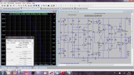
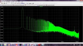
Here I simulated my GaiWire HEC CFB power amp at 50W/8R and THD20k is 0.002225% with 35dB at 20kHz LG.
This CFB is probably to complicated but at the moment I did not succeed with simpler shematic to come close to it.
BR Damir
Attachments
Last edited:
I yet tried to explain why. But it seems words, even consistent from several people, are not enough to convince. So, don't believe: try.
yes I see "words" - not technical arguments, just bald assertions - not even working sim of CFA to compare (with all part models included - unlike your earlier post - which I didn't dismiss - they just don't run in LTspice from your posted files)
I am arguing from Bode Phase Integral "limits of feedback" perspective - we are limited in audio power amp design by the power output devices - practically the drivers too, and triple follower output is still needed if you really want to match VFA high loop gain
bootstrap cascode a diff pair and you can use just a pair 300 MHz ft Q added to the "signal path" count vs CFA front end - which adds negligible speed/phase shift cost to a loop closed around 30 MHz ft ring emitter BJT output Q
CFA still have to provide V gain - using the same class of Q as VFA VAS - which are still faster than output and driver Q in typical audio power amps
I'm not saying CFA is worthless - just that it doesn't have a big inherent advantage over VFA -CFA may be able to improve UGLF ~50% over typical VFA practice - less if VFA used Wurcer's AD797 folded cascode/bootstrapped "VAS"
and if CFA is single pole compensated while VFA practice today does understand 2-pole schemes fairly well then 2a 2-pole compensated VFA can easily beat CFA in loop gain to beyond 20 kHz
do you even know how how to add 2-pole compensation to CFA?
Last edited:
- Status
- This old topic is closed. If you want to reopen this topic, contact a moderator using the "Report Post" button.
- Home
- Amplifiers
- Solid State
- Audio Power Amplifier Design book- Douglas Self wants your opinions