Member
Joined 2009
Paid Member
A few weeks ago I pulled an old Pioneer amp out of the garbage. I pulled out all the boards except the amp and power supply, pulled out all the controls and junk off the front panel.
I was initially intrigued by the amplifier design, it has a lot in common with my first project, the TGM (TGM1) amplifier - http://www.diyaudio.com/forums/solid-state/226482-pioneer-vsx1020-like-tgm1.html
After taking some time to find my around the schematics I was able to get it powered up. With most of the boards scrapped I had to install some jumpers, fix up the grounding scheme, enable the output speaker relays and wire in a temporary volume control on one of the channels.
The original amp was set up with a design target of 2mV across the output emitter resistors. Being a fan of D. Self I adopted the more acceptable target of closer to 25mV.
I didn't want to waste any more time until I'd heard it so I decided today to fire it up. And now that I've heard it, I think it has potential and so I'll be spending a bit more time on this design.
For my initial test I used a PMC speaker, a Sony blu-ray player and a YBA CD player for source material (Pink Floyd Animals and Christy Baron).
Initially I got some hum in the speaker and wondered if my earthing scheme was messed up but it was eliminated by powering off my nearby TGM5 amplifier; the TGM5 has a power supply that leaks flux like nobody's business.
The sound was cleaner from the YBA than from the Sony player. I used my Bryston BP60 amp as a reference amp, with the left channel from the source playing through the Pioneer amplifier and the right channel playing through the Bryston amplifier. The difference between them was not very significant - in fact I was a bit surprised by how good the Pioneer sounded. Ultimately the Bryston sounded cleaner, but the Pioneer amp lost little in terms of bass, treble and overall dynamics. It did have big power on/off thumps though due to how I've set up the power to speaker output relays (speaker protection is enabled and I tested it beforehand using a d.c. source).
So I will do some more cleaning up and consider some further modifications to see if this can become my next generation, "TGM6", amplifier.
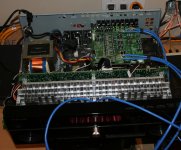
The attached image shows the TGM6 making it's first sound. I've used one of the original pcb's from the amp as a platform to provide RCA inputs and a convenient connection to the amplifier inputs. There's no power to this pcb and so the parts on it are non-functional. I removed some coupling capacitors to provide convenient through-holes to install the blue coloured Cat5 cables you can see. These cables run to the front panel and provide connection for a passive volume control pot (50k Ohm). Sitting inside and on the bottom of the chasis is the power supply pcb along with the output speaker protection relays. You can't see the amplifier pcb here, just the tip of the back of the amplifier but you can see the fins from the heatsink.
EDIT: 25 Jan 2015> TGM6 Reloaded: http://www.diyaudio.com/forums/solid-state/230403-tgm6-amplifier-7-channels.html#post4199133 (post 13)
member 'GrQ' on TGM6.2: "The amp is fine, i keep it at my friend home for usual gathering, remind us about hard working overtime doing this handmade amp lol."
I was initially intrigued by the amplifier design, it has a lot in common with my first project, the TGM (TGM1) amplifier - http://www.diyaudio.com/forums/solid-state/226482-pioneer-vsx1020-like-tgm1.html
After taking some time to find my around the schematics I was able to get it powered up. With most of the boards scrapped I had to install some jumpers, fix up the grounding scheme, enable the output speaker relays and wire in a temporary volume control on one of the channels.
The original amp was set up with a design target of 2mV across the output emitter resistors. Being a fan of D. Self I adopted the more acceptable target of closer to 25mV.
I didn't want to waste any more time until I'd heard it so I decided today to fire it up. And now that I've heard it, I think it has potential and so I'll be spending a bit more time on this design.
For my initial test I used a PMC speaker, a Sony blu-ray player and a YBA CD player for source material (Pink Floyd Animals and Christy Baron).
Initially I got some hum in the speaker and wondered if my earthing scheme was messed up but it was eliminated by powering off my nearby TGM5 amplifier; the TGM5 has a power supply that leaks flux like nobody's business.
The sound was cleaner from the YBA than from the Sony player. I used my Bryston BP60 amp as a reference amp, with the left channel from the source playing through the Pioneer amplifier and the right channel playing through the Bryston amplifier. The difference between them was not very significant - in fact I was a bit surprised by how good the Pioneer sounded. Ultimately the Bryston sounded cleaner, but the Pioneer amp lost little in terms of bass, treble and overall dynamics. It did have big power on/off thumps though due to how I've set up the power to speaker output relays (speaker protection is enabled and I tested it beforehand using a d.c. source).
So I will do some more cleaning up and consider some further modifications to see if this can become my next generation, "TGM6", amplifier.
The attached image shows the TGM6 making it's first sound. I've used one of the original pcb's from the amp as a platform to provide RCA inputs and a convenient connection to the amplifier inputs. There's no power to this pcb and so the parts on it are non-functional. I removed some coupling capacitors to provide convenient through-holes to install the blue coloured Cat5 cables you can see. These cables run to the front panel and provide connection for a passive volume control pot (50k Ohm). Sitting inside and on the bottom of the chasis is the power supply pcb along with the output speaker protection relays. You can't see the amplifier pcb here, just the tip of the back of the amplifier but you can see the fins from the heatsink.
EDIT: 25 Jan 2015> TGM6 Reloaded: http://www.diyaudio.com/forums/solid-state/230403-tgm6-amplifier-7-channels.html#post4199133 (post 13)
member 'GrQ' on TGM6.2: "The amp is fine, i keep it at my friend home for usual gathering, remind us about hard working overtime doing this handmade amp lol."
Attachments
Last edited:
Member
Joined 2009
Paid Member
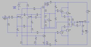
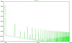
Taking a look at the amplifier: It's a LIN topology, LTP input. It simulates at around 0.01% THD when driving +/-30V into an 8 Ohm resistive load - although I don't have the spice models for the Darlington output devices and used a discrete model instead. The FFT profile is typical and unremarkable.
The LTP has an independent, regulated power supply. This improves PSRR and reduces channel-channel cross-talk. A resistor connects the output to the top of the LTP, modulating the current in step with the signal applied to the bases of the LTP transistors. In theory, like a Gilbert Cell mixer, this results in some creation of harmonic distortion, primarily 2nd order.
Another interesting feature is lack of Cdom phase lag compensation at the VAS. Instead there is resistive load added to the VAS collector and emitter degeneration, plus a resistor + cap from the VAS base to the -ve rail. There is some additional compensation, in the form of phase lead at the feedback node.
If I'm not mistaken, the input is also bootstrapped so input impedance is dominated by the 100K resistor to ground.
Attachments
Member
Joined 2009
Paid Member
I have built-in some additional circuitry to ensure that on power-up the rails to the amplifier come up first, then the speaker relays close after about 8s of delay. On power-down the speaker relays open quickly and the rails to the amplifier take nearly a minute to collapse.
Next I am exploring some changes to the amplifier. The basic design has relatively low nfb so there's a fair bit of differential signal at the LTP. This leads to the problem of the LTP transconductance drooping on large signal swings. Adding degeneration to the LTP flattens the transconductance but the gain drops rapidly so that in the end there's no benefit. A singleton input would have thermal drift issues that I don't want to deal with in this design. What I need is higher OLG gain.
The common solution is a current mirror. I don't want to use a current mirror, it would be difficult to install on the pcb and for various reasons I'm not a fan of them. So how else to reduce the differential signal at the LTP ?
I am looking at two options
1) bootstrap the collector load of the LTP to increase gain. See 1st attachment. There's a useful signal at the emitter of the VAS due to degeneration and as this is a low impedance node it can be used to bootstrap the LTP collector.
2) in addition to 1) I will try a CFP for the VAS. With Cdom compensation in the regular Lin topology the CFP doesn't offer so much benefit since Cdom provides local feedback. But this amp doesn't use regular phase lag compensation so a CFP offers a benefit. It also provides a better buffer between the high impedance bootstrapped LTP and the output devices.
Attachments
Last edited:
Member
Joined 2009
Paid Member
Today I built up TGM6.0 (as per original Pioneer topology), TGM6.1 (bootstrapped LTP) and TGM6.2 (with CFP Vas) - since I have 7 channels I can build them all and compare.
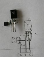
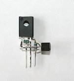
The CFP VAS had to be a pin-compatible replacement for the existing VAS transistor. So some point-to-point wiring was needed to construct a CFP VAS device. See photos.
The CFP VAS had to be a pin-compatible replacement for the existing VAS transistor. So some point-to-point wiring was needed to construct a CFP VAS device. See photos.
Attachments
The common solution is a current mirror. I don't want to use a current mirror, it would be difficult to install on the pcb and for various reasons I'm not a fan of them. So how else to reduce the differential signal at the LTP ?
Implementing a current mirror will somewhat improve the things
but not that dramaticaly and it will be the same if the VAS is
enhanced , only by implementing thoses two mods together
there will be a valuable improvement.
Member
Joined 2009
Paid Member
Well, it would require more surgery on the pcb to implement a mirror. However, all is not lost since with the bootstrap the impedance of the LTP is increased a lot - not as much as a mirror but still higher. With a full mirror it may require more compensation which I'd like to avoid. Then there's the distortion profile - some say 2nd harmonic is benign. A mirror balances the LTP and reduces mostly 2nd harmonic.
I'm sure I could support either solution, but I like the simple bootstrap - which doesn't use a capacitor so it's direct coupled. The input of the LTP is also bootstrapped off the feedback node. And the VAS is bootstrapped. No shortage of boots then.
Measurements with square waves indicated more rounding than I would like to see at 10kHz so I removed the 10pF Cdom from the VAS of 6.1 and 6.2. I didn't find any r.f. instability issues with the CFP.
Listening impressions: the bootstrap isn't working well - it measures terribly with lots of distortion and it sounds like it. Perhaps I have a wiring error as the sims were not this bad. With the LTP bootstrap + CFP Vas it appears to be working well. I'm hearing a cleaner sound with more punch in the bass. Treble is cleaner, cymbals that are splashy on v6.0 (pioneer) are clear on v6.2 (CFP VAS). Cello strings retain more realism with v6.2 (Hadyn). At high volumes with lots of bass the CFP version is clearly tighter. I am very sensitive to treble and apart from sibilance on both amps on one CD (Rod Stewart) I detect no issues with the CFP - good (with TGM2 amplifier with CFP in the LTP I has some concerns over the treble).
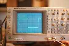
Clipping looks about the same between 6.0 and 6.2, both clip around +/-42V. It's not perfectly symmetrical but it's not far off. When I push it way hard beyond clipping I can see some sticking to the +ve rail - the waveforms are the same for both versions of the amp.
I'm sure I could support either solution, but I like the simple bootstrap - which doesn't use a capacitor so it's direct coupled. The input of the LTP is also bootstrapped off the feedback node. And the VAS is bootstrapped. No shortage of boots then.
Measurements with square waves indicated more rounding than I would like to see at 10kHz so I removed the 10pF Cdom from the VAS of 6.1 and 6.2. I didn't find any r.f. instability issues with the CFP.
Listening impressions: the bootstrap isn't working well - it measures terribly with lots of distortion and it sounds like it. Perhaps I have a wiring error as the sims were not this bad. With the LTP bootstrap + CFP Vas it appears to be working well. I'm hearing a cleaner sound with more punch in the bass. Treble is cleaner, cymbals that are splashy on v6.0 (pioneer) are clear on v6.2 (CFP VAS). Cello strings retain more realism with v6.2 (Hadyn). At high volumes with lots of bass the CFP version is clearly tighter. I am very sensitive to treble and apart from sibilance on both amps on one CD (Rod Stewart) I detect no issues with the CFP - good (with TGM2 amplifier with CFP in the LTP I has some concerns over the treble).
Clipping looks about the same between 6.0 and 6.2, both clip around +/-42V. It's not perfectly symmetrical but it's not far off. When I push it way hard beyond clipping I can see some sticking to the +ve rail - the waveforms are the same for both versions of the amp.
Last edited:
Member
Joined 2009
Paid Member
Hi Wahab, yes it does seem high, a value as you suggest is more common, but the 47R serves some useful purpose. It provides the emitter load necessary to produce a bootstrap voltage for the LTP collector - increasing the effective load impedance and LTP gain considerably. It is also part of the compensation, in reducing the VAS transconductance it helps with closed loop stability. And with the CFP it has been my experience that you need more than 10 - 15R for the CFP to function well - it needs the collector of the slave device to be adequately isolated from the -ve rail so that it can feedback to the VAS emitter master device. All in all I don't think I can change the value.
Member
Joined 2009
Paid Member
Measured small signal frequency response. Sine wave input, +/- 1V into 8 Ohm dummy load measuring amplitude of output using a scope and plotted in Excel. Horizontal axis is Log frequency (kHz), vertical axis is a linear scale, gain normalized to 1 at 2kHz.
I simulated it in spice and it doesn't match as well as I had expected. The measured results show worse low frequency extension but better high frequency extension.
As measured, it shows -3dB points at 4.5 Hz and 500kHz.
I simulated it in spice and it doesn't match as well as I had expected. The measured results show worse low frequency extension but better high frequency extension.
As measured, it shows -3dB points at 4.5 Hz and 500kHz.
Attachments

Last edited:
Member
Joined 2009
Paid Member
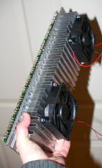
With setting a proper bias for the outputs the heatsink is going to get warmer than the original designers intended. So I've added a couple of low noise fans to the heatsink.
Square wave testing looking good.
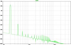
And some distortion FFT plots from Spice showing a very healthy profile.
Square wave testing looking good.
And some distortion FFT plots from Spice showing a very healthy profile.
Attachments
Member
Joined 2009
Paid Member
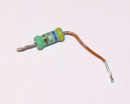
Some more progress. I repaired a blown channel, new emitter resistors, 0R47 and two of them in parallel per output device (see photo of the exploded one) and new output devices. These Sanken output devices are really nice - they feel solid, weighty and very well made.
I also built up some more VAS CFP combinations and installed them all.
I also built up some more VAS CFP combinations and installed them all.
Attachments
Member
Joined 2009
Paid Member
Well the amp sounded pretty good - it was as clean as my Bryston amp. The CFP Vas gives me some extra OLG to play with of course.
However, in TGM6 I used this extra gain for global nfb. I'm not sure this is the right direction although it makes for a fine amplifier it is, like the Bryston, rather honest. I think if there is to be a TGM7 that I will go back to exploring lower gnfb factors.
However, in TGM6 I used this extra gain for global nfb. I'm not sure this is the right direction although it makes for a fine amplifier it is, like the Bryston, rather honest. I think if there is to be a TGM7 that I will go back to exploring lower gnfb factors.
Member
Joined 2009
Paid Member
TGM6 - Reloaded
Well, I obtained a more recent model Pioneer VSX-823-K home theatre receiver. It's only 5 channels, just fine for my use. So time to take a look to see if the amplifier section needs upgrading like TGM6 first version.
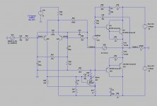
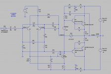
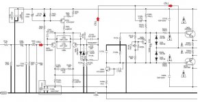
Attached is the schematic for one channel of the amplifier. Some things to note:
Still uses same high performance Sanken Power Darlington output devices. The topology is familiar, LTP input stage, common emitter VAS with bootstrap load.
A couple of key differences though. The LTP tail is now a BJT CCS instead of a resistor fed from a regulated supply rail. The -ve rail of the front end is isolated with a capacitance multiplier (not show in attachment) that is common to all channels.
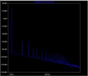
The Service Manual says to set the bias at the output so that there is 2mV across the Re. This is not what D. Self would recommend. Indeed, the FFT looks a bit messy as a result.
Well, I obtained a more recent model Pioneer VSX-823-K home theatre receiver. It's only 5 channels, just fine for my use. So time to take a look to see if the amplifier section needs upgrading like TGM6 first version.
Attached is the schematic for one channel of the amplifier. Some things to note:
Still uses same high performance Sanken Power Darlington output devices. The topology is familiar, LTP input stage, common emitter VAS with bootstrap load.
A couple of key differences though. The LTP tail is now a BJT CCS instead of a resistor fed from a regulated supply rail. The -ve rail of the front end is isolated with a capacitance multiplier (not show in attachment) that is common to all channels.
The Service Manual says to set the bias at the output so that there is 2mV across the Re. This is not what D. Self would recommend. Indeed, the FFT looks a bit messy as a result.
Attachments
Member
Joined 2009
Paid Member
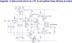
I'm going to take a different path with this upgrade, leaving the VAS untouched and focus on the input stage by adding a current mirror to the LTP.
The current mirror will increase OLG, reducing the differential voltage at the LTP which improves it's performance. LTP's don't have a nice response curve for large signals so higher feedback factors go hand-in-glove with the use of the LTP (in my opinion). The current mirror will also increase the Cdom-limited slew rate and make the slew rate more symmetrical between -ve and +ve going signals. The simulated performance shows an increase in OLG of 10dB with the corresponding improvement in THD, especially higher order harmonics. Phase margin remains good. I could easily remove the VAS degeneration for another 10dB of OLG, but that would compromise phase margin and I don't think it's the right step to take.
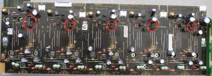
The pcb is hard to work on. Being relatively new it uses lead-free solder which I'd rather not work with. This means working on the top-side of the board. Transistor leads are short making it hard to do edits such as adding LTP degeneration. The most practical approach is to work with resistors and wire links. By removing the Pioneer R14 and R15(link) with wire clippers to leave solderable wire posts I can readily add in a pair of 2N3904's as a current mirror.
So this is what I did today. Installed current mirrors on all channels. Then I tuned up the output bias to give me over 20mV across Re instead of 2mV. I did a soak test to ensure bias was stable. DC offset was also good, less than 10mV on all channels.
The current mirror will increase OLG, reducing the differential voltage at the LTP which improves it's performance. LTP's don't have a nice response curve for large signals so higher feedback factors go hand-in-glove with the use of the LTP (in my opinion). The current mirror will also increase the Cdom-limited slew rate and make the slew rate more symmetrical between -ve and +ve going signals. The simulated performance shows an increase in OLG of 10dB with the corresponding improvement in THD, especially higher order harmonics. Phase margin remains good. I could easily remove the VAS degeneration for another 10dB of OLG, but that would compromise phase margin and I don't think it's the right step to take.
The pcb is hard to work on. Being relatively new it uses lead-free solder which I'd rather not work with. This means working on the top-side of the board. Transistor leads are short making it hard to do edits such as adding LTP degeneration. The most practical approach is to work with resistors and wire links. By removing the Pioneer R14 and R15(link) with wire clippers to leave solderable wire posts I can readily add in a pair of 2N3904's as a current mirror.
So this is what I did today. Installed current mirrors on all channels. Then I tuned up the output bias to give me over 20mV across Re instead of 2mV. I did a soak test to ensure bias was stable. DC offset was also good, less than 10mV on all channels.
Attachments
Last edited:
Hi Gareth
I'm surprised they that Pioneer have used a bootstrap on the VAS on such a modern design! It sure is a very basic looking Linn circuit.
The VAS standing current here is quite low and most practitioners would suggest between 6 - 10mA to swamp the influence of the OPS disturbances. Some individuals (Bonsai, Cordell) would probably advocate increasing the current substantially in the case such as this where an EF2 stage is hanging off the back of it. Consider 20mA+ if within the device Pd ratings and if the device can be suitably heatsinked. I would also increase the bootstrap cap as a loose function of Ic starting with perhaps 220u @ 6mA to perhaps 1m @ 20mA. 47u is probably marginal for good LF response even with the low 3.5mA Ic and smacks of cost-cutting.
The 2N3904 is a general purpose transistor and might not be the best choice for a CM, which has a very low Vce across it and benefits from a device with a low Vsat such as the BC5x0C.
No emitter degeneration on the CM? Groner gives a good explanation why the CM should be degenerated much more than Self suggests.
I'm amazed that Pioneer didn't degenerate the LTP for the cost of two resistors. Actually you will probably get the most benefit by heavily degenerating the input then cranking up the tail current a la Self.
EDIT: that bias generator looks a little overcompensated - possibly to safeguard against and undersized heatsink? Perhaps there is a good reason why the output bias was set so low...
Last edited:
Member
Joined 2009
Paid Member
Christian, don't underestimate the bootstrap. It's cheap and very reliable - both being key qualities for a consumer product. It also sounds good - in fact I have seen that many designers on the forum who have examined and compared the bootstrap with a CCS prefer the sound of the bootstrap. OStripper and AKSA are amongst them.I'm surprised they that Pioneer have used a bootstrap on the VAS on such a modern design! It sure is a very basic looking Linn circuit.
The VAS current is on the low side isn't it. However, the VAS devices don't look to be sized for much power dissipation so it would be risky. At 3.5mA it's workable. The real issue is the output impedance of the VAS, it's quite compromised by the VAS emitter degeneration. I had thought of removing that degeneration but that would push the design over the edge in terms of compensation and require me to re-design it.The VAS standing current here is quite low ...
Most certainly it's cost-cutting, using the smallest size possible. At least the simulated frequency response is more than adequate. It's a home theatre amp, not hi-fi.I would also increase the bootstrap cap ... 47u is probably marginal for good LF response even with the low 3.5mA Ic and smacks of cost-cutting.
That's good information. Too late however!The 2N3904 is a general purpose transistor and might not be the best choice for a CM, which has a very low Vce across it and benefits from a device with a low Vsat such as the BC5x0C.
I read Self on this topic and he says that it will only affect THD at h.f. depending on how well the parts are matched. I used parts from the same batch and judging by the <10mV dc-offset they are pretty good. The design is sub-optimal for good h.f. but my goal here is to clean up the bass and mid-rangeNo emitter degeneration on the CM? Groner gives a good explanation why the CM should be degenerated much more than Self suggests.
This one annoys me the most, it would have been easy for them but now very hard for me to fit them in on the pcbs without quite a bit of surgery - I opted not to do it for that reason.I'm amazed that Pioneer didn't degenerate the LTP for the cost of two resistors. Actually you will probably get the most benefit by heavily degenerating the input then cranking up the tail current a la Self.
Yes it is overcompensated. On power up I get just over 30mV across Re and as it warms up this voltage relaxes to the target value of just over 20mV across Re. It takes 30s to a minute to settle close to the final value.EDIT: that bias generator looks a little overcompensated - possibly to safeguard against and undersized heatsink? Perhaps there is a good reason why the output bias was set so low...
Remember, this is not 'hi-fi', this is about making trivial improvements to a home theatre amp, for use in home theatre. And to make the changes such as to gain significant distortion improvements with minimal effort, risk and expense. Were I looking to make this a hi-fi amplifier, well, I'd simply take the pre-amp signals outside the chassis and use my TGM8
") - something that may still happen. I'd like to encourage others though, who might be interested in using a little knowledge to make some real improvements to their own consumer products - not going crazy here, just to bring them up to a level where they will perform well for their intended purpose.
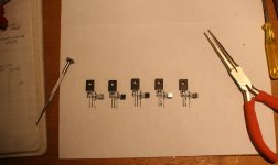
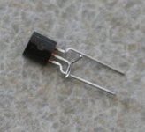
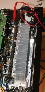
- something that may still happen. I'd like to encourage others though, who might be interested in using a little knowledge to make some real improvements to their own consumer products - not going crazy here, just to bring them up to a level where they will perform well for their intended purpose.Some photos - the 2N3904 for current mirror use, the updated pcbs with the current mirrors installed (shown in red ovals) and then reinstalled into the chassis for bias adjustment.
Attachments
Last edited:
Thanks for sharing those photos and schematic Gareth. I've never bothered to investigate the innards of a HT amp so its a bit of an eye opener. I just assumed they would use a chip (something like an LM3886) for each channel and that 'chip' would house a very sophisticated circuit - probably the ubiquitous Lin/Blameless topology but with ALL the bells and whistles (silicon die space is cheap, copper, iron, and bit 'lytics are not).
If you want a challenge you should design and layout a board(s) that matches the screw fixings and replace the entire card with your preferred circuit
If you want a challenge you should design and layout a board(s) that matches the screw fixings and replace the entire card with your preferred circuit
Member
Joined 2009
Paid Member
These consumer priced HT receivers are bare bones cost wise. I'm not sure how the economics of parts work out though, as you say, a chip amp would seem a cheaper option. I think the issue is specmanship, they have to use +/-54V rails in order to be able to say the amplifier has gobs of power. In reality it's too much, they would be better with less and instead they could spend the money on a better amplifier.
I've thought about doing my own pcbs, but it's a fair bit of effort and there are compromises that I wouldn't want to accept, such as the current power supply design. Overall I suspect the better option is to use external amplifiers with the HT receiver configured as a pre-amp.
If I do get itchy fingers: As Wahab said above, what I should do is upgrade the VAS. With the current mirror on the front, adding in a CFP VAS would be made a compelling story. The CFP VAS will, presumably, have a lower output impedance and do a good job of buffering the input stage from the output stage.
Looking closer at those photos I'm starting to see why they can sell these things for only a few hundred bucks. That "heatsink" appears to be little more than a sheet of folded aluminium flashing. Those resistors look suspiciously like 5% carbon jobbies, and since I don't recognise the markings on those caps, I have to assume they're something cheap and nasty out of China. Even the printed circuit looks cheap - just a piece of single sided phenolic board!!
But having said all that it probably sounds just fine!
Gareth please get your head out of that monstrosity and help us hone TGM8 Unisupply Edition ;-)
But having said all that it probably sounds just fine!
Gareth please get your head out of that monstrosity and help us hone TGM8 Unisupply Edition ;-)
Sorry to keep spamming your thread but your comment about the Sanken outputs had me thinking...
Have you ever worked with the Sanken 2SA1186/2SC2837 pair? Their Pd is only 100W in a TO3P package but the great advantage is their very high fT of 70MHz. I have thought about putting these into a simple EF2 Blameless designed to take advantage of their superior speed. 3 MHz ULGF should be within reach, which could result in a very good performance without resort to sophisticated compensation schemes.
I guess seeing those Sankens (albeit darlington types) and the simple circuit reminded me of a project I wanted to try.
Last edited:
- Home
- Amplifiers
- Solid State
- TGM6 - modified Pioneer HT amplifier