Hello,
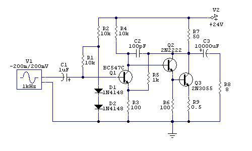
I'm interested to build this amplifier. It is Geoff's from here:
http://www.diyaudio.com/forums/solid-state/213031-simple-amp-circuit-obsevations-3.html#post3043525
because of it's characteristics as:
- Pure class A SE
- no CCS, no quasi, just passive load
- can be driven with average preamps
But I want to scale it up to at least about 5W to 8 ohm.
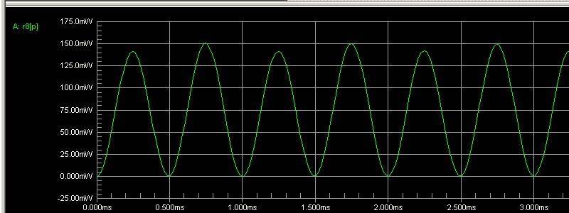
It is good to up 150mW but start to distort at 500mW.
Question:
Is it possible, only with changing component values?
Or circuit must be modified?
Or that 2N3055 just won't go that high?
Thanks")
I'm interested to build this amplifier. It is Geoff's from here:
http://www.diyaudio.com/forums/solid-state/213031-simple-amp-circuit-obsevations-3.html#post3043525
An externally hosted image should be here but it was not working when we last tested it.
because of it's characteristics as:
- Pure class A SE
- no CCS, no quasi, just passive load
- can be driven with average preamps
But I want to scale it up to at least about 5W to 8 ohm.
It is good to up 150mW but start to distort at 500mW.
An externally hosted image should be here but it was not working when we last tested it.
An externally hosted image should be here but it was not working when we last tested it.
Question:
Is it possible, only with changing component values?
Or circuit must be modified?
Or that 2N3055 just won't go that high?
Thanks
The 2n3055 will do just fine.
BUT:
To get 5W you would need 6.32Vrms into the 8R load
This is 8.94Vpeak and 1.11Ap
R7 would have to be a maximum value of (12V-8.94V) 3.05V / 1.11A = 2.73R
At no signal conditions this would mean an Iq of 4.4A (min)
The Hfe (current gain) of the 2n3055 is about 33 at this current.
This makes the collector current of the 2n2222 about .133A and at 11.4V would dissipate about 1.5W
That will not last very long as they are rated for 0.625W.
Now, just to be silly and say it could be done:
If you keep the case temperature of the 2n2222 at -57 deg C then it will dissipate 1.5W without destruction.
To get 5W you need to change R7 and Q2. (And possibly R4)
IMHO
hiktaka:
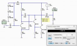
It is impossible to reach an output of 5W in pure class A, with that configuration.
I give an example: with the circuit as it is, you get about 148 mW into 8 ohms with significant distortion. The only way to increase the power output without changing the original scheme is to reduce the resistance R7 from 50 ohms to 8 ohms (similar to the impedance of the speaker), to increase efficiency. But we have to check the power dissipation in the 2N3055 transistor. We also need to verify whether the distortion continues aceptabe yet. We also need to see if the rest of the circuit properly handles the 2N3055 transistor.
The emitter degeneration contributes to lower distortion, but also reduces the efficiency of the amplifier.
With R7 = 8 ohms, the power reaches about 1.77 W approximately. Never reaches 5W.
For maximum efficiency VCQ3 should be adjusted to about 6.66 V.
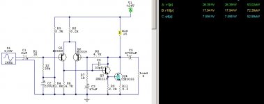
The quiescent current would be about 2.16 A!. The R7 power would be around 37.55 W!. The R9 power would be around 2.34 W!. 2N3055 dissipation would be about 12.09 W!. The power dissipated by the power supply would be 52 W!. The efficiency would be 3.4%.
While it is a more sophisticated and accurate, you can assemble the amplifier "PerfectA", which reaches to 5.1 W per channel into 12 ohms.
regards
PD: DUG: Do not forget the resistor R9!
It is impossible to reach an output of 5W in pure class A, with that configuration.
I give an example: with the circuit as it is, you get about 148 mW into 8 ohms with significant distortion. The only way to increase the power output without changing the original scheme is to reduce the resistance R7 from 50 ohms to 8 ohms (similar to the impedance of the speaker), to increase efficiency. But we have to check the power dissipation in the 2N3055 transistor. We also need to verify whether the distortion continues aceptabe yet. We also need to see if the rest of the circuit properly handles the 2N3055 transistor.
The emitter degeneration contributes to lower distortion, but also reduces the efficiency of the amplifier.
With R7 = 8 ohms, the power reaches about 1.77 W approximately. Never reaches 5W.
For maximum efficiency VCQ3 should be adjusted to about 6.66 V.
The quiescent current would be about 2.16 A!. The R7 power would be around 37.55 W!. The R9 power would be around 2.34 W!. 2N3055 dissipation would be about 12.09 W!. The power dissipated by the power supply would be 52 W!. The efficiency would be 3.4%.
While it is a more sophisticated and accurate, you can assemble the amplifier "PerfectA", which reaches to 5.1 W per channel into 12 ohms.
regards
PD: DUG: Do not forget the resistor R9!
Last edited:
"PD: DUG: Do not forget the resistor R9! "
I did...morning rush, had to go to work.
Yes, R9 needs to go to 0.1R or so.
I still think it could go to 5W but only with a very big heatsink and new Q2.
If I was a complete sucker for a challenge (I usually am), I would design it.
But I don't have time right now.
However, I do agree that if you wanted a good 5W class A it would be better served with a new design.
Thanks
How about replacement:
Q3 >> 2SC2922 (higher power?)
Q2 >> BD139
R7 >> 5 ohm
R9 >> 0.1 ohm
and how to set VCQ3? which resistor to adjust?
But I'd like to keep :
- BJT only, no FET
- Passive load, no CCS
- very inefficient is fine
I will use an SMPS with 24V/100Amp rating + enough filtering, so no issue on PSU.
Again, thanks ..
All those changes are good.Thanks
---
and how to set VCQ3? which resistor to adjust?
---
I will use an SMPS with 24V/100Amp rating + enough filtering, so no issue on
You should add one more diode in the input.
Makes 3 diodes for the first transistor.
This will make the VCQ3 around 10 Vdc.
You can expect output more than 1 Watt RMS with a distortion less than 1.0%
My SPICE simulation did actually gave 1.7 Watt at THD 1.0%
I used 4.7 Ohm and 0.1 Ohm + BD139
and 3 diodes for input.
I offer a table based on some parameters of the original circuit.
The variant is R7. You can see that the best performance is obtained with R7 approximately equal to the impedance of the speaker. The table shows that is with R7 = 7 ohms instead of 8 ohms when you get maximum performance (due to the existence of R9).
The distortion has not been analyzed. It has not been tested if the rest of the circuit can govern large currents, as it is originally.
I hope that this table will be useful.
regards
Attachments
Yes, it is quite true that amplifier is most effective with R=speaker Ohm.
In this case, with a power supply of only 24V we have to make R less than speaker Ohm.
If we want more Watt out.
The goal of 5 Watt RMS out is very optimistic.
I would really be very happy to get 2 Watt.
As mentioned in post above 5 Watt would require a very large heatsink
and very big power resistor load.
We can think maybe 4 resistors at 25 Watt each.
If you are allowed to change the supply voltage, the value of R7, R9 value, replacing any driver transistor, VCQ3:
Vcc = 36.7 V
R7 = 8 ohms (may be lamps in parallel)
R9 = 0.1 ohms
Output power = 5 W RMS into 8 ohms
VCQ3 = 9.4 V
Quiescent current = 3.41 A
Power R7 = 93.17 W (a lot of heat!)
Power R9 = 0.86 W (reasonable)
Power Q3 = 30.91 W (also reasonable)
Power Supply Power: 108.76 W (possible)
Efficiency: 4.6% (not high but it looks interesting)
regards
PD: Get good filtering at low voltage and high current is very difficult.
Should raise the supply voltage if the PSRR is not very high.
Last edited:
How about this one?
Diff. input stagw, higher gain and a rather reasonable idle dissipation
Again, thanks ...
That circuit looks a little better. The output power is about 0.9 W into 8 ohms. It is not insignificant if we use efficient speakers. The distortion is lower than the previous design. DF is higher (can be read as a good thing).
regards
- Status
- This old topic is closed. If you want to reopen this topic, contact a moderator using the "Report Post" button.
- Home
- Amplifiers
- Solid State
- How to scale up this SE class A ?