Hi!
Is there someone who has already built it?
JFET Input High Speed MOSFET Power Amplifier PCB Telos | eBay
Greets:
Tyimo
Is there someone who has already built it?
JFET Input High Speed MOSFET Power Amplifier PCB Telos | eBay
Greets:
Tyimo
Same question too!Does anyone know what comprises the output stage in this amplifier?
")
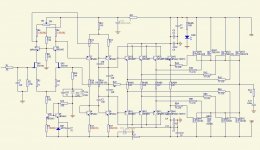
I have the schematic of these amplifier.
The Telos compare to the Minesis much cheaper amplifier (new price was $14 000).
If I read well the circuit each mosfet has it own driver so it must be matched very well.
The orig used MPSA43/93 but someone replaced in the circuit with 42/92 because that more commonly produced (available).
I was interested on these amp but after people built the Minesis and their result report, I think I stick with my mosfet amplifier.
After Wahab sim outperform the Minesis all do in real life was not tested yet. But soon will be..
Greets G.
The Telos compare to the Minesis much cheaper amplifier (new price was $14 000).
If I read well the circuit each mosfet has it own driver so it must be matched very well.
The orig used MPSA43/93 but someone replaced in the circuit with 42/92 because that more commonly produced (available).
I was interested on these amp but after people built the Minesis and their result report
, I think I stick with my mosfet amplifier.After Wahab sim outperform the Minesis all do in real life was not tested yet. But soon will be..
Greets G.
Attachments
Goldmund is offering private sales online of demo and out of production models.
Never seen that before. There sales must be dropping.
https://sales.goldmund.com/
Never seen that before. There sales must be dropping.
https://sales.goldmund.com/
Hello Cuda
Yes you right..
These Telos is a older model (I believe no longer in production). I was interested on these amp (clone) to. Someone offered the stuffed PC boards for $240.
Orig. sold for $14 000 so it can not be so bad no to test it specially now you can get the PC boards.
I will see how will perform my amp, on sim easily outperformed the Goldmund M. which was cloned. But we all know between sim and real sound can be huge difference.
In case I'm not satisfied with my amp probably I'll test these GM clone.
Since I have the semis for..
I know peoples who have successfully built an amp using that pcb and parts list and it sounded fine. However I would think there could be some issues in some case where the MOSFET have a very high VGSoff where the resulting bias would be too low. There is no procedure provided to the builder to adjust specifically for a target bias. I am pretty sure that the real Goldmund amps have all similar bias... But what is it?
Fab
Fab
Last edited:
Where do I connect my multimeter probes to check the bias (Jims Audio boards) and how many need it to be max ?
You will have to do some calculations.
You have to use an ammeter inserted between eirher the positive or negative PSU lead and amplifier PSU entry point. That will give you the total current of the amp. You can also insert a small value (ex:0.1 to 1 ohm) and use a voltmeter to determine the total current.
After that you need to measure the current from the 3 previous stages:
1) 1st differential stage: with a voltmeter one resistor( in current source ) voltage drop divided by resistor value.
2) 2nd diff stage: same thing but single resistor at top side of schematics.
3) driver stage: one emitter bjt voltage divided resistor value.
Assuming that you have 4 matched driver transistors and 4 matched output Mosfet by polarity, The individual Mosfet bias current is:
(Total current - (1st diff current - 2nd diff current - 4*(driver current)) / 4
To adjust the bias you will have to do the reverse calculation.
The max bias current is determined by you and must not give a heatsink too hot. It must be at least 110ma as explained in previous post. In mine I used about 150ma to 180ma per Mosfet if I remember.
Fab
Last edited:
No easier way ?
Why's that ?
After that you need to measure the current from the 3 previous stages:
1) 1st differential stage: with a voltmeter one resistor( in current source ) voltage drop divided by resistor value.
2) 2nd diff stage: same thing but single resistor at top side of schematics.
3) driver stage: one emitter bjt voltage divided resistor value.
Last edited:
Yes you can simply calculate 1st and 2nd stage and also approximate the driver stage. For example , 1st stage is 6.2v/R8. Or you can simply use about 30ma for the sum of all stages except the output stage. So measure total current and substract the calculated and approximated values(30ma).
Then you divide by the number of mosfet for one polarity (4).
Fab
Then you divide by the number of mosfet for one polarity (4).
Fab
Last edited:
Maybe silly question but why is that all needed ?Can't you just insert a 10 OHM resistor in the positive powerline and measure across it and adjust R18 ?
Read again 1st paragraph of post 15... ...... with 10 ohms there would be too much voltage drop...
Referring to post 15 again, I think I ended up more to about 130ma or so per Mosfet.
According to schematics of post 5, it is R16.
Fab
Last edited:
- Status
- This old topic is closed. If you want to reopen this topic, contact a moderator using the "Report Post" button.
- Home
- Amplifiers
- Solid State
- Jim's Audio Goldmund Telos 390 clone