Epcos
@ JMFahey
Can You point out which particular Epcos series are sound-wise Yours best choice ?
Thnx,
Andreas
In fact, I use EPCOS exclusively, I use "regular" EPCOS,
But if you want to go for the best of the best, be my guest .
Certainly can't hurt")
@ JMFahey
Can You point out which particular Epcos series are sound-wise Yours best choice ?
Thnx,
Andreas
Yes.
Truth is, and going to the bottom of the problem, that those Sikorel are very good.
No doubt about that.
In fact, I use EPCOS exclusively, they are the best available in my market, period.
It's just that some parameter, measured in V/uSec and referred to overheating , was mixed with Amplifier slew rate, which does use same units, but for a different purpose.
Nothing beyond that.
By the way, I use "regular" EPCOS, no need to approach "Computer Grade " capacitors or similar spec.
I'd have to order the full box through ARROW or AVNET.
But if you want to go for the best of the best, be my guest .
Certainly can't hurt
I believe its B41550 sikorel original version tech acquired by Epcos but there are two things..
1. On the reviews its said that Halcro has lean bass and not impressive in < 100Hz bass frequencies..
2. What is the option shall we go with 7 x 1500uf caps or one 10000uf cap ?
even im about to order the only prob is lead time of 12weeks..
Dear smiley09 and rhythmandsandy.
Being an Engineer with 43 years experience building amplifiers commercially, and with the feet firmly on the ground, I don't care much about uncontrolled "listening tests" and "Magazine Reviews".
I prefer EPCOS for the very good reason that they are a "serious" company, I've been using them for said 43 years (since February 1969 to be precise, when I cloned my first Fender Bassman), for so long that I witnessed their colour change: from original "S&H" silver to yellow to "Siemens" orange to EPCOS black, go figure.
Always consistent, solid, long lasting, reasonable price, what's not to like?
"Sound" ?????
They are reservoir caps, holding a certain voltage between charging pulses, and providing current on demand.
Nothing more, nothing less.
Sound is made by the amplifier, not the PSU.
True, but only when both are properly designed by someone who can do both arithmetic and algebra.JMFahey said:Sound is made by the amplifier, not the PSU.
did anybody try Alcon the specs look even better than Epcos..
http://www.icd-sales.com/Manufacturers/Alcon/spec-sheets/PG6DI ICD.pdf
http://www.icd-sales.com/Manufacturers/Alcon/spec-sheets/PG6DI ICD.pdf
Better?
Better at what?
Slightly better ESR or impedance?
I have capacitors of an "nonfamous" brands here with even better ESR, slightly poorer impedanse and actually better leakage currents. Where does this place my caps?
As Fahey states earlier here, the capacitors in the PSU are there to store some energy, for the amplifier to use from on demand. (Together with the energy actually provided by the transformer) There is not very much to it.
And it has an unbelieveable little influence to the amplifiers slewrate in the amp anyway.
I am willing to go so far that an amplifier and its PSU wich is engineered in an adequate proper manner would give no influence to either the slewrate neither the sound as for the capacitors in the powersupply. If the cap there is named Jenssen, Epcos, BC, Vishay or "FengPeng" would do the job regardless.
The timeconstant even gets worse as the capacitance increases. Guess where this leads? There should actually be no problem getting the same timeconstant on a bad ESR-cap, opposed to a fenomenal good ESR-cap. But really one should look at the impedance of the cap instead. And what curvature the cap can show us out of that parameter.
That would tell us much more of how fast the capacitor is able to deliver this peak in current (keeping its voltage at a certain level) at the frequencies in speak.
My PSUs contains sufficient capacitance to provide energy to the amp when the transformer is "on vacation" (Read, have its voltage on a level lower than the requiresd to present any voltage in speak on the amplifiers output.
If my PSU doesn't deliver this required voltage, I add some more.
Result: Better ESR, Better Impedance, Better PSU. And this regardless what vcapacitor I use. I like it.
Sound is made by the amplifier, not the PSU.
I completely agree with everything you've said. The following is really nothing but semantics. But what "makes the sound" could be thought of in more than one way.
When a layman sees an amplifier, the PSU is included in the term "amplifier". And after all, the two must work together, to make any sound.
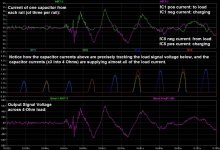
But the fact remains that the sound we actually hear is rather-directly created by the PSU current (which is merely "modulated" by the amplifier). The PSU is providing the energy to make the sound. So in that sense, the PSU is making the sound, but under the control of the amplifier portion.
Also, the large majority of the current that makes the sound comes from the reservoir and decoupling caps. See the attached image from an LT-Spice simulation. This was discussed more-thoroughly around the post at http://www.diyaudio.com/forums/power-supplies/216409-power-supply-resevoir-size-38.html#post3117390 .
None of this makes much difference, except maybe in the way that people think about how an amplifier works. I have found it to be a useful construct to use in order to help clarify both my own and other people's understandings of how amplifiers work. (It's also sometimes amusing to use just to "tweak" certain electrolytic-hating people who pretend that "the signal path" does not include the PSU.)
I too do not see how, with a properly-engineered PSU, different makes or models of reservoir caps could affect the sound. I suspect that when differences have been heard, it was because the design or implementation was marginal in some way, which allowed the differences to affect the PSU performance.
Keep up the great work.
Cheers,
Tom
Attachments
Dear smiley09 and rhythmandsandy.
Being an Engineer with 43 years experience building amplifiers commercially, and with the feet firmly on the ground, I don't care much about uncontrolled "listening tests" and "Magazine Reviews".
I prefer EPCOS for the very good reason that they are a "serious" company, I've been using them for said 43 years (since February 1969 to be precise, when I cloned my first Fender Bassman), for so long that I witnessed their colour change: from original "S&H" silver to yellow to "Siemens" orange to EPCOS black, go figure.
Always consistent, solid, long lasting, reasonable price, what's not to like?
"Sound" ?????
They are reservoir caps, holding a certain voltage between charging pulses, and providing current on demand.
Nothing more, nothing less.
Sound is made by the amplifier, not the PSU.
i agree on generic mathematical terms it seems obvious about the cap but what makes Mundorf or Epcos sound different as users say they are very good... Nichicon is not bad being used by even nelson or krell or plinius etc... but i saw only Halcro using it.. apart from stability it does has sonic benefits...
we might say that all other caps might be 90% good so Epcos are 95%? in the sense they are better and intended as ideal capacitors?
SIKOREL
I was curious about EPCOS 'better' properties and I found the only SIKOREL line - (ex. SIEMENS-SIKOREL) stand out from the rest of ordinary EPCOS range of capacitors. The ex SIEMENS-SIKOREL (screw type) ELCAPS are made for extreme high current pulses with a special electrolyte mixed with xx ? formulation and a special (foils) winding technique was used to be minimal high current pulses inertia affected (internal vibrations (electrolyte + foils)) and to have as constant as possible impedance, inductance from lowest to highest pulse charges and they are purposely made for high speed, high current switching power supplies for the military equipments.
Maybe this is the reason for theirs High Cost and if used in AUDIO PSUs an 'absence' of a classic ElCap PSU capacitors signature on sound (perception) as many audio related reviews point it out ?
Rgds.
Andreas
- Being an Engineer with 43 years experience building amplifiers commercially, and with the feet firmly on the ground . . .
-----------------------------------------------------------------------
@ rhythmsandy
- we might say that all other caps might be 90% good so Epcos are 95%? in the sense they are better and intended as ideal capacitors?
I was curious about EPCOS 'better' properties and I found the only SIKOREL line - (ex. SIEMENS-SIKOREL) stand out from the rest of ordinary EPCOS range of capacitors. The ex SIEMENS-SIKOREL (screw type) ELCAPS are made for extreme high current pulses with a special electrolyte mixed with xx ? formulation and a special (foils) winding technique was used to be minimal high current pulses inertia affected (internal vibrations (electrolyte + foils)) and to have as constant as possible impedance, inductance from lowest to highest pulse charges and they are purposely made for high speed, high current switching power supplies for the military equipments.
Maybe this is the reason for theirs High Cost and if used in AUDIO PSUs an 'absence' of a classic ElCap PSU capacitors signature on sound (perception) as many audio related reviews point it out ?
Rgds.
Andreas
if its just esr then why cant use 100 x 100uf caps in parallel to achieve in micro ohms thus more beneficial? isnt that a good solution? or having one or two big 20000uf in parallel along with them does do the job perfect..
You bring up a good point. But it's probably the inductance (ESL) that hurts more, rather than the ESR. However, we can kill both of those with the same stone.
I think that having very low inductance, AS SEEN BY the power pins of the output devices, is necessary in order to enable getting the most-accurate transient response. And I think that accurate transient response is extremely important, and it is very easy to get wrong, and usually can't be gotten right without special design effort focused on it, even for "just audio". It's difficult to get the inductance low-enough, usually, simply due to the conductor lengths that are necessitated by the physical sizes of the caps, and their lead spacing.
Aside: Degradations due to physical implementation and layout factors probably almost always outweigh the small differences in the intrinsic qualities of the caps, in every real-world design. Many people are silly about it. Instead of taking the easy way, buying special components looking for a magic cure, they should spend some of their time and energy to learn to get everything ELSE right, first, because only then could they have a valid platform to use to evaluate any other changes. Silly people buy special caps but use long runs of tiny wire to connect them (more ESL and ESR), and leave large loops and large enclosed loop areas throughout (antennas), and use improper grounding topology (bouncing input voltage reference points), and ignore RF filtering and ignore proper bypassing, and for decoupling they don't calculate what minimum capacitance and maximum inductance are required, and merely guess at what total reservoir capacitance is needed, and what transformer parameters to use, and many other things that should be "de rigeur".
Worrying about what special caps to use, before getting all of those BASICS optimized, in like chasing your tail, or spinning your wheels: It's fun, but you never get anywhere.
But yes, an array of 10 x 10 caps, say 2200 uF to 10000 uF each (or some prefer smaller, like 330 uF), on UNBROKEN copper planes of two-sided PCB, an array for each rail, would be excellent, as long as both sets of planes could get within a couple of millimeters of the power and ground pins of the output devices.
For example, with 10 x 10 1000 uF, on 1mm thick PCB, in square array, with rectifiers feeding at middle of one side of square and output devices at middle of opposite side of square, the output devices should see only about 0.5 nH of inductance between power and ground planes, PLUS the inductance of the connections from the planes to the silicon (which would be way more than 0.5 nH, no doubt). Check out everything you can find by Terry Given, on diyaudio. For the cap array pcb implementation, he did leave us a few good morsels to find. I collected his relevant posts about that in a series of links at the bottom of the post at http://www.diyaudio.com/forums/chip-amps/224914-lm3886-component-selection-3.html#post3282640 .
BUT, for low bass frequencies, even THAT wouldn't get the impedance down to anywhere near the 1 milliohm range. It would take about EIGHT FARADS, to get 1 milliohm impedance down at 20 Hz (which still doesn't count the connecting conductors' impedances). So maybe you could use a 28 x 28 array of 10000 uF caps, per rail (it won't matter what kind of caps they are; trust me). But, as FAS42 pointed out recently, it might be better to use a special REGULATOR, instead of so many caps, if we found that we really needed the low impedance to extend down to 20 Hz.
Cheers,
Tom
Last edited:
Fortunately we don't need to get the cap's own impedance down in the 20Hz range, if it does double duty as both reservoir and smoother. This is because the rectifier will clamp it every 10ms/8.33ms so its effective impedance is likely to be reduced for all frequencies below 100/120Hz. A switched/clamped capacitor can have a low impedance right down to DC! Some people on here may be too young to remember switched-capacitor filters, where a capacitor acts as a variable resistor in a filter circuit.gootee said:BUT, for low bass frequencies, even THAT wouldn't get the impedance down to anywhere near the 1 milliohm range. It would take about EIGHT FARADS, to get 1 milliohm impedance down at 20 Hz (which still doesn't count the connecting conductors' impedances).
Power supplies have to be designed. That means, first, understanding them. Having designed a PSU people may then, if they wish to, spend money on special components for purposes of bragging, fashion or marketing. Simply throwing 10's of mF of expensive boutique capacitance at a PSU is not design.
- Status
- This old topic is closed. If you want to reopen this topic, contact a moderator using the "Report Post" button.
- Home
- Amplifiers
- Solid State
- Relation between RC time constant of psu cap and slew rate