how fast the capacitors has to be to give higher slew rate?
Is there any connection regarding the slew rates and the psu RC time constant?
Example:
I just have a doubt that in general the amplifier just acts like modulator for the reserve power at the psu. Now I just wanted to know when an amp has slew rate of 50V/us the psu should deliver the required power that much fast and it has to come from the psu. When its coming from the psu it has to be from the capacitors. Here the discharge time from the capacitor is calculated from the RC time constant which is take an example:
if we take a decent psu cap which is 10000uf and with esr of 10 milli ohm the discharge time is 100ms which is way too slow discharge than the slew required. Is this calculation correct?
so do we need seriously fast capacitors or with capacitors having super low esr like 0.000001 to achieve the slew?
Last edited:
The high-power output current must come from the PSU. Where else?
Unless your music only plays during the charging pulses, the current comes from the PSU caps, or from decoupling caps.
The slew rate of the CURRENT is not governed by the RC time constant. The INITIAL current amplitude seems to depend only on the ESR, plus any other series R in the circuit, and the change in the voltage across the cap. That simple impedance relationship, delta i = delta V / ESR+R is only valid for a short time. The CURRENT slew rate during that short time is probably limited mostly by the ESL plus the inductance of the conductors. The current can usually slew rather-blindingly fast. But placing decoupling caps very near the point of load is necessary, for the fastest response (and the least rail voltage change).
We are lucky that the current's slew rate is not tied to the voltage's slew rate, or vice versa, since we want the voltage to not change quickly, or by much.
Last edited:
So the time constant is a voltage function. The capacitor doesn't want to give up its voltage, and will supply current to maintain it. The slewing amp will take that supplied current and convert it to the voltage it needs. Is that more or less correct, and does it help visualize the action?
The capacitor is very happy "to give up its voltage". The only thing preventing it is issues like resistance and inductance; these come from both the circuit and the capacitor internals. Amplifier slew rates are rarely limited by supply caps, but often by amplifier loop stability measures such as dominant pole caps. In the rare case where the PSU is the limit, just raise the transformer secondary voltage a little to give more headroom or improve the wiring to the caps.
To see it from a different (but matching) point of view: PSU RC constants do not matter much, if any.if we take a decent psu cap which is 10000uf and with esr of 10 milli ohm the discharge time is 100ms which is way too slow discharge than the slew required. Is this calculation correct?
so do we need seriously fast capacitors or with capacitors having super low esr like 0.000001 to achieve the slew?
Why?
1) ESR is just "another" resistance in series with the load.
.001 ohm or .01 ohm, won't make a difference.
Now, 0.1 ohm will start to be noticed, not as a "Slew Rate limiter" but simply as a lossy resistor in series.
2) capacitance determines how much will voltage drop during that current pulse.
Simply stated, higher PSU capacitance will not make the amp any "slower" .
If any, it will "help" it by keeping a steadier supply voltage.
And what does that phrase exactly mean?so my question is that how does caps like Siemens Sikorels have faster transients?
i saw the info reg slew rate over 100v/us using sikorel
Solid State Power Amplifier Supply Part 1
Solid State Power Amplifier Supply Part 1
I thought that a capacitor resists a change in its voltage, and would create current to maintain it. An inductor resists a change in current, and would create voltage to maintain it. Is this just an oversimplification?The capacitor is very happy "to give up its voltage".
check the post no 31: stating about how Epcos is stating on the slew rate of the caps..
http://www.diyaudio.com/forums/chip...ring-caps-do-influence-sound-gainclone-4.html
http://www.diyaudio.com/forums/chip...ring-caps-do-influence-sound-gainclone-4.html
A capacitor does not create a current in order to maintain its voltage. On the contrary, the rest of the circuit creates a current in order to change the capacitor voltage. Without a current the capacitor will maintain its voltage.sofaspud said:I thought that a capacitor resists a change in its voltage, and would create current to maintain it.
As post 31 clearly states the slew rate is a rating for the caps, not a value. It doesn't tell you what they can do; it tells you what your circuit shouldn't do. Ripple current rating is the same: a restriction on use, not a guarantee of performance. In both cases the likely reason is internal heating of the capacitor, leading eventually to failure.rhythmsandy said:check the post no 31: stating about how Epcos is stating on the slew rate of the caps..
Sorry but the guy who wrote http://www.tnt-audio.com/clinica/ssps1_e.html has no clue about capacitors ... or tries to sell you some Mojo (or profit) filled stuff.
Reservoir Capacitors (that's what PSU capacitors are) have no "Slew Rate" or rather, they are the exact opposite of that concept: a perfect, huge PSU capacitor would have no voltage variation between its terminals under load, behaving as a perfect voltage and current source.
While the Slew Rate concept is based on voltage variation .
Ok, ok, but these are *real* capacitors, and *their* voltage across terminals does vary with load.
Can we calculate it?
Yes, of course.
>>>>>>>>>>>>>>>>>>>
Capacitors and calculus
Capacitors do not have a stable "resistance" as conductors do. However, there is a definite mathematical relationship between voltage and current for a capacitor, as follows:

<<<<<<<<<<<<<<<<<<<
Crunching some numbers and using values supplied by your link
I (Amperes)=C (Farads) 40 (Volts)/1 x 10^-6 (Second)=
I= (10000/10^6) x 40 x 10^6 (Amperes).
Simplifying 10^6 we end up with:
I = 10000 x 40 (Amperes)=400000 Amperes.
So yes, you *can* Slew 40V/uSec across a 10000 uF capacitor; you "only" need 400000 Amperes to do it.
Source or sink, your choice.
As of the Sikorels, you'd need 1000000 Amperes to achieve that.
Good luck with that.
Reservoir Capacitors (that's what PSU capacitors are) have no "Slew Rate" or rather, they are the exact opposite of that concept: a perfect, huge PSU capacitor would have no voltage variation between its terminals under load, behaving as a perfect voltage and current source.
While the Slew Rate concept is based on voltage variation .
Ok, ok, but these are *real* capacitors, and *their* voltage across terminals does vary with load.
Can we calculate it?
Yes, of course.
>>>>>>>>>>>>>>>>>>>
Capacitors and calculus
Capacitors do not have a stable "resistance" as conductors do. However, there is a definite mathematical relationship between voltage and current for a capacitor, as follows:
<<<<<<<<<<<<<<<<<<<
Crunching some numbers and using values supplied by your link
let's start with 40V/uS , the value *they* state can be achieved by a regular commercial quality capacitor.a typical commercial value capacitor, rated at 10,000uF/63V and costing some Euro 8-9, will have a speed of 30-40V/uS at best. An equivalent Elna for Audio series black, costing some Euro 15-25, will have a speed in the range of 80-90V/uS, i.e. at the very worst, double the speed of the best case in commercial cap land. A Siemens Sikorel cap, costing some Euro 20-30, will slew at over 100V/uS - but at a price.
I (Amperes)=C (Farads) 40 (Volts)/1 x 10^-6 (Second)=
I= (10000/10^6) x 40 x 10^6 (Amperes).
Simplifying 10^6 we end up with:
I = 10000 x 40 (Amperes)=400000 Amperes.
So yes, you *can* Slew 40V/uSec across a 10000 uF capacitor; you "only" need 400000 Amperes to do it.
Source or sink, your choice.
As of the Sikorels, you'd need 1000000 Amperes to achieve that.
Good luck with that.
Last edited:
Gotcha. Thanks. I knew my perspective here is/was fuzzy.A capacitor does not create a current in order to maintain its voltage. On the contrary, the rest of the circuit creates a current in order to change the capacitor voltage. Without a current the capacitor will maintain its voltage.
agreed its all about the current which goes through the capacitor and for such a super crazy Amperes I really dont think so. So what makes Sikorel so different as people say that its supposed to be the best... nelson doesnt use it.. neither krell I see that only Halcro using it... on the reviews its said that the amp has the speed....
Actually, you can get all kinds of crazy-sounding numbers for capacitors' voltage slew rates. But if the equations you use take into account ESR and maybe ESL, the crazy-sounding numbers will be pretty close to correct. However, it's often only for a VERY short time.
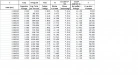
Even just the reservoir caps in a PSU behave in ways that were, to me, somewhat unexpected. You can see for yourself by either running LT-Spice simulations or running the PSU spreadsheet that I uploaded as an attachment to the post at http://www.diyaudio.com/forums/power-supplies/216409-power-supply-resevoir-size-167.html#post3287619 .
Attached is a small sample of the numbers that the spreadsheet plots after performing the numerical solution of the differential equations for a transformer-rectifier-capacitor-load power supply circuit (including transformer winding leakage inductance and resistance). The attachment shows the numbers during the initial part of the first startup pulse of a particular PSU.
It would be very easy to get almost any VOLTAGE slew rate you wanted, out of almost any cap (although they might explode if you over-do it). With small-value caps, it's quite easy.
Since i = C dv/dt, and dv/dt is the voltage slew rate, just solve for that:
dv/dt = i / C
Obviously, for SMALLER values of C, the same current, i, would cause a larger voltage slew rate.
If you put 10 amps into a 0.1 uF cap, it would give 10 A / 0.0000001 F = 100 million volts per second, which would be 100 Volts per microsecond.
But if you're talkiing about a larger capacitance, the ONLY way to get a high voltage slew rate to occur would be to put in or take out a VERY LARGE current.
BUT, I don't know why anyone would care about a cap's VOLTAGE slew rate. We use caps to provide CURRENT TRANSIENTS, by lowering the voltage across the cap by a very small amount (for example, when an output transistor is commanded to lower its channel resistance in order to let more current flow, which will lower the rail voltage slightly, making the decoupling and/or reservoir caps provide exactly the right surge of current). INITIALLY, for a short time, the cap will obey the impedance equation:
∆v / ∆i = ESR
or
∆i = ∆v / ESR
(but other circuit series resistance would need to be added to ESR, if the cap was in a circuit)
That equation means that for a lower ESR, the cap will have an initial transient current with a greater amplitude, but will reach that higher amplitude in the same amount of time. Or, you could say that it would reach the same current as before in less time. So it would be faster, in terms of current tranients.
Just playing around:
Actually, since initially, for a linear (ramp) change in voltage, versus time, the impedance relationship holds:
∆v / ∆i = ESR
But we also know that
∆i = C ∆v / ∆t
which can be rearranged to
∆v / ∆i = ∆t / C (impedance in seconds per Farad?)
we could also say
∆v / ∆i = ∆t / C = ESR (i.e. larger-value caps have lower ESR)
or
∆t = ESR ∙ C (an RC time constant?)
Also, an approximate ESR equation is
ESR = 0.02 / (C ∙ VR)
where VR is an electrolytic cap's voltage rating.
That gives
∆t = ESR ∙ C
and
∆t = 0.02 / VR
which seems to imply that electrolytic caps with higher voltage ratings should have lower ESR, for the same capacitance value.
Anyway, for a linear current ramp versus time of ∆i Amps in ∆t seconds, into a capacitor with ESR = Resr, the change in the cap's voltage would be:
∆v = ∆i ( ( ∆t / ( 2 C ) ) + Resr )
If it was a constant current instead of a ramp, for ∆t seconds, that would change to:
∆v = i ( ( ∆t / C ) + Resr )
or
∆v = i ∙ ( ∆t / C ) + Resr ∙ i
which also implies that caps with higher ESR would have a larger ripple voltage for a given PSU load current.
For the same load current, the ripple voltage amplitude with a cap with a higher ESR would be larger by the average load current times the difference in ESR valus.
Attachments
Yes.
Truth is, and going to the bottom of the problem, that those Sikorel are very good.
No doubt about that.
In fact, I use EPCOS exclusively, they are the best available in my market, period.
It's just that some parameter, measured in V/uSec and referred to overheating , was mixed with Amplifier slew rate, which does use same units, but for a different purpose.
Nothing beyond that.
By the way, I use "regular" EPCOS, no need to approach "Computer Grade " capacitors or similar spec.
I'd have to order the full box through ARROW or AVNET.
But if you want to go for the best of the best, be my guest .
Certainly can't hurt")
Truth is, and going to the bottom of the problem, that those Sikorel are very good.
No doubt about that.
In fact, I use EPCOS exclusively, they are the best available in my market, period.
It's just that some parameter, measured in V/uSec and referred to overheating , was mixed with Amplifier slew rate, which does use same units, but for a different purpose.
Nothing beyond that.
By the way, I use "regular" EPCOS, no need to approach "Computer Grade " capacitors or similar spec.
I'd have to order the full box through ARROW or AVNET.
But if you want to go for the best of the best, be my guest .
Certainly can't hurt
- Status
- This old topic is closed. If you want to reopen this topic, contact a moderator using the "Report Post" button.
- Home
- Amplifiers
- Solid State
- Relation between RC time constant of psu cap and slew rate