Hi
I have a couple of old MF Dr Thomas power amps, both of which are still working well and I'm keen to give them a thorough refresh to keep them reliable, hopefully improving the sound quality as well! In original form, they sound fairly relaxed with good solid bass and a rather effortless power delivery. Surprising poke for their rated 120w RMS.
Has anyone experience of these amps? They seem to be very simple in their design and construction - which appeals a lot.
Initial plan is to fit new, larger smoothing caps, a better bridge rectifier, replace all the caps on the circuit board with higher grade items and replace all the rather flimsy internal wiring with decent stuff. What about diodes and transistors? Any likely improvements to be made there?
Any recommendations as to what make of components and any other mods that can be carried out would be gratefully received.
Would anyone be interested in seeing photos of the refurbishment?
Thanks in advance!
Hi
Good to see that someone else also believes in the Dr T. I also own a few Dr T's and I have always thought the Dr T a good amplifier.
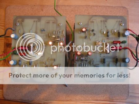
I think the real strength of the amplifier is the Hitachi Mosfets used in the output stage as I think they produce a very natural sound. The amplifier also uses the simple circuit that Hitachi designed for use with their mosfets. I find it still holds its own against modern circuits. Also in this amplifier the large transformer of 650va and large power supply capacitors of 15,000uf per rail help give a solid bass and good transients.
I upgraded my amplifiers a while ago. I changed all the electrolytic capacitors on the pcb's and replaced them with 105 degree types - basic 105 degree types from Rapid electronics. I do not think that increasing the values of any of these will make any improvement. I also changed the power supply capacitors which also made a big improvement to the sound. I fitted 15,000uf 100v capacitors to replace the existing 15,000uf, 60 v capacitors fitted by MF. The amplifier runs on power supply lines of +/- 62v so I thought the original 60v capacitors were under rated and replaced them with 100v capacitors. I used Kendeil capacitors ( type 1 from memory ) for the power supply.
I do not believe that replacing the small transistors on the pcb will make any noticable improvement. You could use slightly lower noise transistors for the input stage differential pair but I do not think you would hear any improvement. As mentioned earlier I would no change the output transistors. I do not think there any better output transistors - or even as good - available today.
The internal wiring looks a biy messy as you say but, it works and on my amplifiers the wiring was all of sufficient size. There are no earth loops and no huming from the amplifier.
In summary I found benefits from changing out the electrolytic capacitors on the pcb's and from changing the power supply capacitors. Changing the power supply capacitors made the biggest improvement.
If you want to try other changes I would imagine that adding another bridge rectifier and having a dedicated rectifier per channel would help but I have not tried this.
Hope this helps.
Don
Good to see that someone else also believes in the Dr T. I also own a few Dr T's and I have always thought the Dr T a good amplifier.
I think the real strength of the amplifier is the Hitachi Mosfets used in the output stage as I think they produce a very natural sound. The amplifier also uses the simple circuit that Hitachi designed for use with their mosfets. I find it still holds its own against modern circuits. Also in this amplifier the large transformer of 650va and large power supply capacitors of 15,000uf per rail help give a solid bass and good transients.
I upgraded my amplifiers a while ago. I changed all the electrolytic capacitors on the pcb's and replaced them with 105 degree types - basic 105 degree types from Rapid electronics. I do not think that increasing the values of any of these will make any improvement. I also changed the power supply capacitors which also made a big improvement to the sound. I fitted 15,000uf 100v capacitors to replace the existing 15,000uf, 60 v capacitors fitted by MF. The amplifier runs on power supply lines of +/- 62v so I thought the original 60v capacitors were under rated and replaced them with 100v capacitors. I used Kendeil capacitors ( type 1 from memory ) for the power supply.
I do not believe that replacing the small transistors on the pcb will make any noticable improvement. You could use slightly lower noise transistors for the input stage differential pair but I do not think you would hear any improvement. As mentioned earlier I would no change the output transistors. I do not think there any better output transistors - or even as good - available today.
The internal wiring looks a biy messy as you say but, it works and on my amplifiers the wiring was all of sufficient size. There are no earth loops and no huming from the amplifier.
In summary I found benefits from changing out the electrolytic capacitors on the pcb's and from changing the power supply capacitors. Changing the power supply capacitors made the biggest improvement.
If you want to try other changes I would imagine that adding another bridge rectifier and having a dedicated rectifier per channel would help but I have not tried this.
Hope this helps.
Don
") :
:ok! I'll post photos along the way. Can't find a schematic anywhere, unfortunately. There are so few components that I've decided to change all the caps (12), resistors (22) and diodes (10).
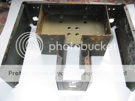
First job is to blast and repaint the case. This particular one, newly acquired, looks like it has sat in a puddle for a while and is a bit rusty inside. It still works perfectly though.
I'm pondering on the idea of doubling up the power supplies and having separate transformers etc for each channel. Any thoughts?
Hi
Doubling up transformers will not really help as the transformer ( 650 VA ) is already more capable than the output stage of both channels added together.
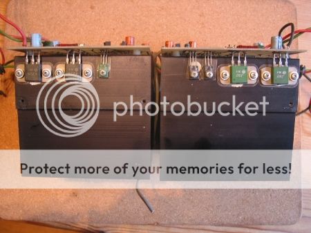
A check on the spec sheet for the output mosfets will show they can deliver 5 amps per device. Two mosfets in parallel gives 10 amp current from the output stage. The way to get more power would be to add more output mosfets. However the mosfets are expensive and need to be matched to each other.
Changing the existing power supply capacitors to higher current handling capacitors will help as the original ones fitted do not handle high current - that is why I mentioned changing to such as Kendeil capacitors in the power supply.
Don
Doubling up transformers will not really help as the transformer ( 650 VA ) is already more capable than the output stage of both channels added together.
A check on the spec sheet for the output mosfets will show they can deliver 5 amps per device. Two mosfets in parallel gives 10 amp current from the output stage. The way to get more power would be to add more output mosfets. However the mosfets are expensive and need to be matched to each other.
Changing the existing power supply capacitors to higher current handling capacitors will help as the original ones fitted do not handle high current - that is why I mentioned changing to such as Kendeil capacitors in the power supply.
Don


Hi,
i am new to the forum and was looking for some information on this amplifier when i cam about this thread. Basically i have just purchased a Dr Thomas (being a lover of retro musical fidelity amps), however i got it cheap due to the fact that it had been abused by it's previous owner who dropped it and then decided to take a saw to the front of it???
The amp works fine but i need to get the dimension of the outer case to try and fabricate another one. Are any of you able to assist me with this, i will post a picture of the "butchered" front later for you to see.
Thanks.
- Status
- This old topic is closed. If you want to reopen this topic, contact a moderator using the "Report Post" button.
- Home
- Amplifiers
- Solid State
- Dr Thomas Power Amp Improvements