Hey everyone,
I recently acquired this amp (Yamaha AX-730) off a family friend who didn't want it because it was "Dead".
I have never had many dealings with amps and am still trying to get my head around speaker/crossover design however I thought I would take a look.
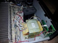
Anyway, from what I can figure the power transformer (see photo) is blown. I have 240v across the primary, however 0V across both sets of the secondary taps.
Is this strange/unusual? My train of thought with this is either it has blown the primary winding (which being on the low current side I thought this seemed unlikely) or both secondary windings blew at once (again, how likely is that?).
Or, am I missing something?
Regardless, I'm sure it'll have to be replaced anyway I was just curious as to the cause!
So I guess the question is where can I get a new one from (in Australia preferably)?
According to this thread (http://www.diyaudio.com/forums/chip-amps/71568-first-gainclone-ax-730-transformer-question.html) it has dual 17v and 46v taps.
Again, being new to amplifiers I don't even know where to start, so any suggestions/websites would be appreciated!
I had a quick look in Jaycar but to be honest I didn't know exactly what to look for so quit ha.
Thanks,
Felix.
I recently acquired this amp (Yamaha AX-730) off a family friend who didn't want it because it was "Dead".
I have never had many dealings with amps and am still trying to get my head around speaker/crossover design however I thought I would take a look.
Anyway, from what I can figure the power transformer (see photo) is blown. I have 240v across the primary, however 0V across both sets of the secondary taps.
Is this strange/unusual? My train of thought with this is either it has blown the primary winding (which being on the low current side I thought this seemed unlikely) or both secondary windings blew at once (again, how likely is that?).
Or, am I missing something?
Regardless, I'm sure it'll have to be replaced anyway I was just curious as to the cause!
So I guess the question is where can I get a new one from (in Australia preferably)?
According to this thread (http://www.diyaudio.com/forums/chip-amps/71568-first-gainclone-ax-730-transformer-question.html) it has dual 17v and 46v taps.
Again, being new to amplifiers I don't even know where to start, so any suggestions/websites would be appreciated!
I had a quick look in Jaycar but to be honest I didn't know exactly what to look for so quit ha.
Thanks,
Felix.
Attachments
E-I transformers
There once were large 46V-0-46V, 15-0-15V E-I style transformers retailed in Oz but not now, AFAIK.
I think you will need 2 Toroids there, if they'll fit. Perhaps a 300VA model with 2 x 45V windings and a
smaller 50 VA toroid with 2x18V windings will be needed if you just want to buy from stock. Check the
current ratings first. These could be attached to the rear panel, with a litlle bracing, but don't use
the mounting bolt for anything other than simply holding the transformer down (unless you want to add
a shorted turn and a heap of trouble, that is!)
I think Altronics will be the only retail source, as I suspect ordering a single E-I custom build, a rewind
or finding a donor wreck won't appeal much anyway!
Checked if there is any accessible thermal fuse in the cirquitry for the primary windings?
Transformers more often blow their primary windings.
Actually I haven't seen more than just ONE transformers where the secondary winding was blown.
(And that perticular transformer was engineered in an incorrect manner)
Do You have a multimeter? Check each of the primnary windings (I guess there is at least two of them) and see if there is any conductivity in them.
Alsi between the (possible) two windings there could me either connections to a voltage selector switch, or to a thermal fuse.
A closeup picture of the transformer would help.
Last edited:
Hey guys, Thanks for all your replies!
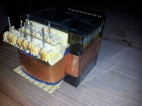
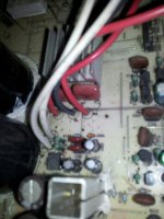
Pulled the transformer out (see photo's), no continuity on the primary side however secondary's were fine as predicted!
Started pulling it apart and am at the point now as shown in the photo...
Do I have to fully delaminate the core to gain access? Is there any (easy) way of doing this? It seems the laminates are strip welded together so I could get the grinder out....
I'll look for a replacement regardless, I just wouldn't mind taking it apart at checking this fuse for my own curiosity!
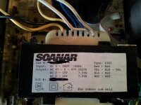
Ian - I've been looking around and have sourced some Toroids. However, I did stumble across this EI. Transformer 47-0-47 3A Centre Tapped 2 x 15 500mA - Jaycar Electronics.
Would this suit? If I use the centre tap to get 2x47v and the two 15v? Slight different voltage from specified however not too bad?
I can't find any current ratings on my amp/in the manual I found online and there seems to be little info about this unit. Apparently it's 110w/channel@8 ohm so would this 300VA transformer be suffice? My quick mathematics say yes however being such a newbie to Amps I need an expert!
Thanks again for all your inputs!
Felix.
Pulled the transformer out (see photo's), no continuity on the primary side however secondary's were fine as predicted!
Started pulling it apart and am at the point now as shown in the photo...
Do I have to fully delaminate the core to gain access? Is there any (easy) way of doing this? It seems the laminates are strip welded together so I could get the grinder out....
I'll look for a replacement regardless, I just wouldn't mind taking it apart at checking this fuse for my own curiosity!
Ian - I've been looking around and have sourced some Toroids. However, I did stumble across this EI. Transformer 47-0-47 3A Centre Tapped 2 x 15 500mA - Jaycar Electronics.
Would this suit? If I use the centre tap to get 2x47v and the two 15v? Slight different voltage from specified however not too bad?
I can't find any current ratings on my amp/in the manual I found online and there seems to be little info about this unit. Apparently it's 110w/channel@8 ohm so would this 300VA transformer be suffice? My quick mathematics say yes however being such a newbie to Amps I need an expert!
Thanks again for all your inputs!
Felix.
Attachments
Transformer 47-0-47 3A Centre Tapped 2 x 15 500mA - Jaycar Electronics
Yes, that's the unit, but it seems less current than I recall and probably not enough for the amplifier on any but 8R loads. As a stopgap replacement, it would be acceptable, provided you didn't try to run the amplifier into low impedance (<6R) speakers or invite the gang around and party with it, as someone always tries out what volume knobs can do to get attention.
The other concern is how much current is needed for the low voltage secondaries. If they are only used to supply the control circuits, relay and the preamp at no more than 15V, no problem. (look at the size/rating of the smaller rectifier bridge or diodes.)
A crude but effective comparison is to compare weight but whaddayaknow, a heavy item and Jaycar don't state shipping weight even! 'Pity, but I think it will be a bit anaemic in the role. 47VAC suggests about 65V rails and 130W/8R, so I think a bit more current, around 5A, would be more appropriate for 4R loads. That gets expensive.
Thanks Ian.
Currently I'm not in full need of this amp, however I've been wanting to set up a nice rig in my bedroom for some easy listening. Given I'm not planning to be running this on my main setup (where the walls rigidity gets a working) this transformer would be suitable provided an 8 ohm load?
150w/channel @ 6R, which would be pushing it. This amp never recommended a 4R so I'll make sure when I get around to building my room gear I'll aim for 8R.
I've had a look at the preamp circuitry for the 15v secondary's, however I'm unsure what to look for exactly. I think I might just wing it and give it a go. I might head into my local Jaycar and see if I can get a weight from them...
Finally, in anyone's opinion is this amp worth saving/spending money on?
From what I've heard this is from the days of wonderful Japanese electronics before the big Yamaha sellout. Any thoughts on this?
Thanks again,
Felix.
Edit: Thinking about this now this sound really silly in that connecting the other ends to the 0v of the main secondary would try and pull it down to -15v. So it must be just 1x15 line for the preamp?
Hi again,
Went into Jaycar today and inspected the transformer, decided it looked of reasonable build quality so I purchased it.
Got all excited and screwed it in and now have a slight problem.
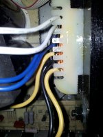
With the 15v secondary's (in the pictures the blue and white wires) there are two of them. With the previous transformer there was only the white. So, assuming each is its own 15v, does this mean my amp only takes one of the sets of wires (requiring 1x15v for the preamp) and leaving the other ones not connected.
Or, would it need 2x15v meaning 1 blue and 1 white going into the PCB and other 2 tied to the 0v (black) of the other secondary?
I'm not sure how the old transformer was wired, maybe these other two were tied to the 0v line internally, or maybe this new transformer has a another 15v line that I just won't be using?
Does that make sense? I guess summing up is would my preamp need 2 15v supplies or just one? Maybe i'm over thinking it....
I don't want to blow anything up
Cheers,
Felix.
Hi again,
Went into Jaycar today and inspected the transformer, decided it looked of reasonable build quality so I purchased it.
Got all excited and screwed it in and now have a slight problem.
With the 15v secondary's (in the pictures the blue and white wires) there are two of them. With the previous transformer there was only the white. So, assuming each is its own 15v, does this mean my amp only takes one of the sets of wires (requiring 1x15v for the preamp) and leaving the other ones not connected.
Or, would it need 2x15v meaning 1 blue and 1 white going into the PCB and other 2 tied to the 0v (black) of the other secondary?
I'm not sure how the old transformer was wired, maybe these other two were tied to the 0v line internally, or maybe this new transformer has a another 15v line that I just won't be using?
Does that make sense? I guess summing up is would my preamp need 2 15v supplies or just one? Maybe i'm over thinking it....
I don't want to blow anything up
Cheers,
Felix.
Attachments
Last edited:
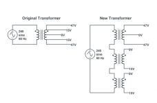
Got it all back out again today and for something that should be relatively simple I can't quite get my head around it.
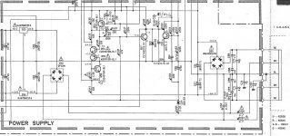
After doing some continuity checks with my multimeter this attached diagram is what I suspect is happening. I've also attached the circuit diagram for the power supply into the amp. It seems the two 15v lines are both going into a full wave dc rectifier then into some voltage regulator IC's. Once I get this connection from the transformer sorted I should be able to test it from there...
So, Should I be fine to tie the 0V lines together (Forming effectively a 47-15-0-15-47 as the original transformer) provided I pick the right phase wires?
Cheers,
Felix
Attachments
Not the two 0V.
The 0V and 15V between the 15V windings should be connected together and to GND, and ultimately together with the centertap on the two 47V windings.
Then the two 47V ends to the rectifier to the right, and the two remaining 15V ends to the fuses in front of the rectifier to the left.
The original transformer seems to have 2X15V + 2 32V windings on each end of the 2X15V. Funny arrangement.
To take it lead for lead on the transformer at the left in your post:
47V to the point ending at the top of C93 (Right side of the rectifier to the right)
0V to the point ending at the bottom of C95
47V to the point ending at the bottom of C94 (Left side of the rectifier to the right)
15V to the point ending in FuseResistor R156
0V to the point ending at the bottom of C95
15V to the point ending at the bottom of C95
0V to the point ending at the Fuseresistor R157
All this providing that the manufactorer of the transformer has provided a drawing one can trust.
Last edited:
Hey,TANDBERGEREN - Thanks for that! It was pretty much what I had in my head on connecting the two 15v's in series, but thanks for confirming and giving such a detailed response! It really helped =)Amp is now working, had it running before and it all sounds good, all the controls work. Thanks again everyone for the advice! Now just to build a pair of speakers for it to run.....Cheers,Felix.
- Status
- This old topic is closed. If you want to reopen this topic, contact a moderator using the "Report Post" button.
- Home
- Amplifiers
- Solid State
- Yamaha AX-730 Replacement Transformer