there we go ...since the one and only published a class AB schematic based on TIP142-147 which i actually think is very bad and over dated only because is depending on those transistors but also cause darlington topology shucks to my understanding .
Said to my shelf not much happening in class AB so i may as well go back ( like NP did ) and draw a schematic based on 1970 technologies with a few upgrades to gain topology and semis .
So we have the G amp which G stands for Geriatric
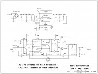
The design is simple i choose to run it of 63V regulated power supply and as we speak its working on a vero board producing amazingly sweet bass crisp high and very clear mids...Next step will be to produce a proper pcb and then measure or debug
highlights :
The common heatsink of the LM 317HVT will also provide thermal protection and the regulated power supply sziklai style is pretty quick ,very quiet , and capable of almost 3.5A well enough to supply one Chanel ( intention is to keep i dual mono or mono block and pcb will be based on that )
The design is very free and you are welcome to criticize ,contribute ,debug ,simulate and comment on
Kind
regards
sakis

Said to my shelf not much happening in class AB so i may as well go back ( like NP did
) and draw a schematic based on 1970 technologies with a few upgrades to gain topology and semis . So we have the G amp which G stands for Geriatric
The design is simple i choose to run it of 63V regulated power supply and as we speak its working on a vero board producing amazingly sweet bass crisp high and very clear mids...Next step will be to produce a proper pcb and then measure or debug
highlights :
The common heatsink of the LM 317HVT will also provide thermal protection and the regulated power supply sziklai style is pretty quick ,very quiet , and capable of almost 3.5A well enough to supply one Chanel ( intention is to keep i dual mono or mono block and pcb will be based on that )
The design is very free and you are welcome to criticize ,contribute ,debug ,simulate and comment on
Kind
regards
sakis
Lovely amplifier dear Sakis...this kind of circuit sounds really nice
Maybe will not measure very well...but sound is awesome.
Very good supply also.
Congratulations...you have listened and you are feeling the sound is warm and touch our hearts.... i do feel the same when i listen this kind of unit.
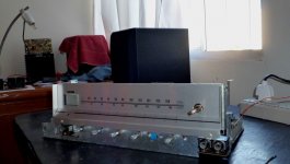
This is what i am doing rigth now Sakis.... a very old style (1970) system that i receive as a gift..was dismantled but i could not kill it because the lovely radio reception.... it goes playing that old style (distorted) sound, filled with crazy harmonics...but sent me back to my good old days.
The circuit is alike yours...not that different.
Will make a picture now!
regards,
Carlos
Maybe will not measure very well...but sound is awesome.
Very good supply also.
Congratulations...you have listened and you are feeling the sound is warm and touch our hearts.... i do feel the same when i listen this kind of unit.
This is what i am doing rigth now Sakis.... a very old style (1970) system that i receive as a gift..was dismantled but i could not kill it because the lovely radio reception.... it goes playing that old style (distorted) sound, filled with crazy harmonics...but sent me back to my good old days.
The circuit is alike yours...not that different.
Will make a picture now!
regards,
Carlos
Attachments
Last edited:
thanks for thinking. I qualify to build this, I'm retired.
Is there supposed to be a dot (connection) between the rightmost 4700 uf cap and the speaker out, or does the output transistor junction just connector to the 4700 uf cap which connects only to the 560 ohm resistor which connects to ground?
Congratulations, I think this is a single supply amp which could be protected against shorts by a single 3300 uf cap between output and speaker, without the stupid noises back to back electrolytic caps make when they go through zero volts. Unlike the MJR7 which I have been thinking about, this design has parts you can buy at distributors. The MJR7 fets come mainly from counterfeiters. I've been collecting parts to clone off the dynakit ST120 for organ replacement amps, but this design looks more modern. Simpler, too, without the 7 transistor djoffe bias board required to solve crossover distortion on the ST120. 30 W, 8 ohm speakers is what organs need. I need no closely spaced IC leads to be bridged with the soldering iron. This qualifies, all leaded discrete parts.
Last edited:
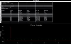
This one may sound very good because the ratio in between third and second harmonic
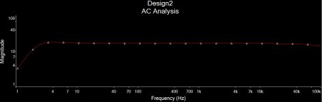
Despite harmonic distortion is very high (0.5%) at 18 Watts RMS output (8 ohms) it may sound very good, because flat and because the harmonic distribution.
Harmonics, compared now a days is huge... 250 times bigger...but this produces nice effect too.
We use to worry a lot..but speakers, itself, already produces much more than that in distortion...so...the exercise of harmonic reduction is just academic.
What means 0.001% distortion compared to speaker 1 percent?.... you just do not listen the amplifier quality...you listen the speaker bad quality (all them are terrible!)
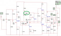
I have simulated....made a fast simulation, have adjusted only the green circle resistor that i found needed.
I have not spent too much time on it...i do think we can reduce this distortion tuning and tweaking this amplifier..distortion of 0.05% is possible and this will represent 10 times less than i could have...i am busy with other things, i have just made simulation because Sakis is an old friend..but you can do a lot on this circuit to make it even better.
Organs, the nice sound we have from them, are because harmonics!
regards,
Carlos
Despite harmonic distortion is very high (0.5%) at 18 Watts RMS output (8 ohms) it may sound very good, because flat and because the harmonic distribution.
Harmonics, compared now a days is huge... 250 times bigger...but this produces nice effect too.
We use to worry a lot..but speakers, itself, already produces much more than that in distortion...so...the exercise of harmonic reduction is just academic.
What means 0.001% distortion compared to speaker 1 percent?.... you just do not listen the amplifier quality...you listen the speaker bad quality (all them are terrible!)
I have simulated....made a fast simulation, have adjusted only the green circle resistor that i found needed.
I have not spent too much time on it...i do think we can reduce this distortion tuning and tweaking this amplifier..distortion of 0.05% is possible and this will represent 10 times less than i could have...i am busy with other things, i have just made simulation because Sakis is an old friend..but you can do a lot on this circuit to make it even better.
Organs, the nice sound we have from them, are because harmonics!
regards,
Carlos
Attachments
Last edited:
You see...this kind of circuit from the seventies, sounds nice
Despite distortion is very high.
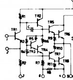
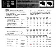
Look it is the same circuit used into the STK435 audio amplifier integrated circuit..the one i am listening..the one i have published the picture.
Look the THD, and the schematic..almost the same.
Hammond organ produces a lot of harmonics and we love this!
http://www.youtube.com/watch?v=Pi_gwED-gQw
regards,
Carlos
Despite distortion is very high.
Look it is the same circuit used into the STK435 audio amplifier integrated circuit..the one i am listening..the one i have published the picture.
Look the THD, and the schematic..almost the same.
Hammond organ produces a lot of harmonics and we love this!
http://www.youtube.com/watch?v=Pi_gwED-gQw
regards,
Carlos
Attachments
Last edited:
Hi Sakis
Well, you have tried something different. Fantastic!
I think perhaps you could look at the trace connection "dots" of the output capacitors on the schematic, as Indianajo queries. It looks a bit confusing as to what is connected and what is not, though I'm sure DX has it right with a parallel connection for 10,000uF in his Multisim draft.
Congratulations and keep up the geriatric ideas - this one looks very interesting.
as about the resistor is a typing error it supposed to be 4K7 than 47K thank for pointing out
as about the output .... dont exactly understand what i ve done wrong but its supposed to be like that
output from transistors goes to a bank of caps
output of caps is feeding the output
while feedback senses from the output
while loaded with a resistor to ground
while accommodating a zobel in the output to ground
kind regards
sakis
PS
I am not really crazy about simulators ....id like to built and measure ...tweak from there she how it goes
Hi Sakis,
Look at the second 4,700uf output cap. The bottom (-) connection has no dot. (signifying no connection to the output). When there is no conflict, like a T junction, no need for a dot. For a X junction, it can be either a junction or a crossing.
So, to be obvious, it looks like only one 4,700uf output cap and another 4,700uf in series with 560R to ground. Of course, I hope I know better but maybe.... I don't?
My article ""the G amp"" while G means Geriatric was based on that concept and was found not to have that much interest anyway http://www.diyaudio.com/forums/solid-state/229120-g-amp.html
I missed this thread for unknown reason. Do you have pcb design tested and debuged?
PCB is not made yet ...It will be done with in August which is a vocation month for non audio people ...
In between one placed a question regarding power supply and if hypothetically there was another regulated power supply of a few volts more say 5-10 to supply with different voltage first stage and output
Comments on that please ... my estimation is that will create a better clipping condition if and ever needed but the real question is if its expected to improve overall performance and increase dynamics .
Kind regards
Sakis
Still listening. 4700 uf output caps are SO cool as speaker and output transistor protection compared to the 30 part (and growing) relay protection circuit I'm building for my PV-1.3k. I've bought 100 VCT 1.5 amp transformers (to use one side), MJ15015 , TIP41-42C, and MPS8099 instead of your European transistor selection. I did buy a couple of actual LM317HVT's for the regulator, assuming it has something to do with decreasing bias current when hot.
As far as clipping, I've never heard any, but I'm running the NTE181 output transistors on my ST120 at 80 V rail, so with a 1.5 Vpp (8 ohm) start to Tchaikovsky's 1812 Overture the cannon shots don't cause clipping. We'll see what 63 v rail does in your original design.
As far as clipping, I've never heard any, but I'm running the NTE181 output transistors on my ST120 at 80 V rail, so with a 1.5 Vpp (8 ohm) start to Tchaikovsky's 1812 Overture the cannon shots don't cause clipping. We'll see what 63 v rail does in your original design.
- Status
- This old topic is closed. If you want to reopen this topic, contact a moderator using the "Report Post" button.
- Home
- Amplifiers
- Solid State
- the G amp ....