Ok....chop chop time....some work done today:
All aparently bad components removed...capacitors only removed to clean the board better...and they have the plastic burned...so new ones...
Left Side cleaned:
Right side cleaned:
What do you think? ready to apply araldite?")
All aparently bad components removed...capacitors only removed to clean the board better...and they have the plastic burned...so new ones...
An externally hosted image should be here but it was not working when we last tested it.
Left Side cleaned:
An externally hosted image should be here but it was not working when we last tested it.
Right side cleaned:
An externally hosted image should be here but it was not working when we last tested it.
What do you think? ready to apply araldite?
Good.. the left side damage is not too bad. Unfortunately the right side is, but I'm sure it can be salvaged.
That TIP2955 looks suspicious to me... the ST logo does not look right. I'd say it was a fake (though why anyone would fake a 2955 is beyond me!). ST have certainly never made them in that package style - older ones were TO-218 (as the TIP3055 is) and modern ones are TO-247 style.
The amp does have all the signs of either having been run into a short, or run excessively loaded which caused output device failure.
From looking at the circuit board, it looks like Q11/Q12 and Q111/Q112 have been replaced with the wrong devices - looks like BC546/556 have been used. Evidently these transistors failed and when the guy who did the repair couldnt find FST239/240, he decided to use those.
They are not up to the job unfortunately. ZTX653/753 is the correct replacement.
They are not up to the job unfortunately. ZTX653/753 is the correct replacement.
Good.. the left side damage is not too bad. Unfortunately the right side is, but I'm sure it can be salvaged.
That TIP2955 looks suspicious to me... the ST logo does not look right. I'd say it was a fake (though why anyone would fake a 2955 is beyond me!). ST have certainly never made them in that package style - older ones were TO-218 (as the TIP3055 is) and modern ones are TO-247 style.
The amp does have all the signs of either having been run into a short, or run excessively loaded which caused output device failure.
Yeah looks a little suspicious to me too....:S
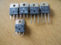
I take them all out...take a look at this pic:
An externally hosted image should be here but it was not working when we last tested it.
Those are similar to the ones I have here.
ST never seemed to label their transistors two batches alike.
But nice job with the "sunny side". How about the essential one?
The circuit side it's ok...the only spot that need to do some circuit repair is te one that have a hole...i will take a photo before repair with Araldit because now i put some tape to do a base for fill with the glue...will post a pic late today...
From looking at the circuit board, it looks like Q11/Q12 and Q111/Q112 have been replaced with the wrong devices - looks like BC546/556 have been used. Evidently these transistors failed and when the guy who did the repair couldnt find FST239/240, he decided to use those.
They are not up to the job unfortunately. ZTX653/753 is the correct replacement.
As soon as i get home i will check this components...but yes...they look different from the other transistors on this amp...the side that have letters are grey...this is what take my attention....i will take a look too see if the solder are intact or not.....
I could be wrong and the TIP2955 are genuine, but I cant find any ST datasheet that shows that they made them in a TO-3P package - only the original TO-218 package, and now the more modern TO-247 package. The only versions of them I can find that were made this way, are Chinese copies which are probably inferior quality.
Anyway, they should both have been replaced, IMO. As the repair attempt appears to have failed, I would replace both sets of transistors again to be certain that they are not faulty.
The original Q(1)11/Q(1)12 should look much like Q7/Q107 does. This is called the E-Line package. If you can't get the ZTX653/753, I would say BC639/640 could work - but they have a different pinout, so you will have to bend the leads to fit in the right place.
Ok...so i do a "short list" and will play safe and replace the following components:
FUSES:
2x FUSE 2A/250v
1x FUSE 630ma T
----------------------------------------
LEFT SIDE:
Q13 -> TIP3055 (TO-218) or (TO-247)
Q14 -> TIP2955 (TO-218) or (TO-247)
---------------
R28
R35
R37
R38
R39
R40
---------------
D1
---------------
C14
C15
C16
---------------
FST239/240 replacement-> ZTX653/753
Q12
Q11
---------------
RV1 -> Iskra 1k
----------------------------------------
RIGHT SIDE:
Q113 -> TIP3055 (TO-218) or (TO-247)
Q114 -> TIP2955 (TO-218) or (TO-247)
---------------
R128
R135
R137
R138
R139
R140
---------------
D101
---------------
C114
C115
C116
---------------
FST239/240 replacement-> ZTX653/753
Q112
Q111
---------------
RV101 -> Iskra 1k
----------------------------------------
I think i don't forgot anything.....and correct me if i'm wrong...
Regarding the C14/C114 the original one it's a little different capacitor...do you guys know the original brand from the one int the left side?
The components are so cheap so I would say yes. Change the lot.
You could change the cooked bits only to miss one failed component only to have to change them all again.
You can of course take everything out and test every last component. It's labour intensive but at least you will know that everything is OK.
Caps are difficult to test so change them anyway.
You could change the cooked bits only to miss one failed component only to have to change them all again.
You can of course take everything out and test every last component. It's labour intensive but at least you will know that everything is OK.
Caps are difficult to test so change them anyway.
Last edited:
Q(1)11/Q(1)12 already removed...look what was there:
https://www.dropbox.com/s/22chnnv0gfum6j8/2013-02-01 18.17.15.jpghttps://www.dropbox.com/s/l57td6cn7f...2018.17.15.jpg
https://www.dropbox.com/s/22chnnv0gfum6j8/2013-02-01 18.17.15.jpghttps://www.dropbox.com/s/l57td6cn7f...2018.17.15.jpg
Last edited:
BC546B and BC559C... a poor repair attempt by someone who did not know what they were doing....
I would agree - you might as well fit all new transistors as it is quite cheap to do so. You may use BC546/BC556 if they are easier to obtain, instead of BC547/557. You may replace all resistors with metal film (blue) as well.
I'd suggest mounting the resistors that are part of the VI limiting circuit (R31-38 and R131-138) spaced away from the pcb by 10mm - make a bend in the leads to support them.
C14/114 will have been a polystyrene 10pF capacitor. Polystyrene is now pretty much obsolete, so you may use a polypropylene or polyester film capacitor here, or a high stability (COG/NPO dielectric) ceramic capacitor. 1% tolerance or better. I notice again the previous repairer was an idiot and just used a regular ceramic capacitor to replace this part - this probably caused oscillation which caused the damage you have now!
The two BC547 (Q2, Q3, Q102, Q103) in the input of the amp should be matched types.
Unless you meassure something wrong with those, leavbe them to be.
Probably is also the Q4, Q5 and Q6 also OK. Theese are less critical being matched, but always an advantage.
From Q7 and outwards I would change them all even if they meassure well.
Q1/Q11 is only for the muting. Leave them to be.
Q8 should be a MPSA056
If You can't get it, I have some here.
I could be wrong and the TIP2955 are genuine, but I cant find any ST datasheet that shows that they made them in a TO-3P package - only the original TO-218 package, and now the more modern TO-247 package. The only versions of them I can find that were made this way, are Chinese copies which are probably inferior quality.
.
Here: TIP3055 pdf, TIP3055 description, TIP3055 datasheets, TIP3055 view ::: ALLDATASHEET :::
Clearly states it has been produced in both TO-247-package as TO-3P
I must say I have had good experience with the Chineese so far.
Got good parts all the way.
Actually the only seller that have provided me with fake parts was from somewhere else, and that seller never was in sight anymore.
Bought replacements from China and I am good. (And for $9,- getting me ten transistors. Nice)
Last edited:
You are right about Chineese and even On-semi TIP3055/2955 being supplied in what was called SOT93 case.Clearly states it has been produced in both TO-247-package as TO-3P
.....Bought replacements from China and I am good. (And for $9,- getting me ten transistors. Nice)
The issue is, I think, about ST Micro product being in anything other than TO218 or TO247 packages.
That's either a plain metal tab or full plastic case. When you see a SOT93 case [similar to T03P
] labelled ST, then also check old data sheets, you would also think "Fake".
Why the big deal with ST product? Well, some TIP3055 are no better than original 2N3055 spec, with Ft 800 kHz.
ST product exceeds 4MHz and distortion is considerably lower in 50W amplifiers I have built - lower even than
other branded TIP3055 products. I think that's what ARCAM were doing there, using something you wouldn't
normally consider suitable for Hi-fi.
The two BC547 (Q2, Q3, Q102, Q103) in the input of the amp should be matched types.
Unless you meassure something wrong with those, leavbe them to be.
Probably is also the Q4, Q5 and Q6 also OK. Theese are less critical being matched, but always an advantage.
From Q7 and outwards I would change them all even if they meassure well.
Q1/Q11 is only for the muting. Leave them to be.
Q8 should be a MPSA056
If You can't get it, I have some here.
A little bit late...i already remove every single transistor from both sides....
I will try to find Q8 here in portugal...i let you know if i can't get it....thanks!
So...this night i cover the holes with Araldite...not too much eyecandy...but i think will do the job...what do you guys think?
An externally hosted image should be here but it was not working when we last tested it.
An externally hosted image should be here but it was not working when we last tested it.
The big hole will be cover one more time before i drill the holes....
Last edited:
OK.
You should find two and two transistors to be matched to eachother for the position Q2 and Q3 (Q102 and Q103) at the least.
I would go for a complete match of both theese and the Q4 and Q5 in the input part of the amp.
Will secure as good sound as possible in the amp.
Actually the rest is not that critcal, as there is only singelstanding transistors who only interacts with its partner of opposite charge. (TIP2955/TIP3055, FST239/FST240, and so on)
Otherwise your repair seems to be fine. I would have used polyester for repair, but this is of only academic interrest. Looking good what You are doing anyhow.
The main reason to match the Q2/Q3 transistors is to ensure low DC offset at the output. To match them, use a hFE tester on a multimeter. Pick two transistors where the value is close as possible.
Q8 should be MPSA56 - made by either Onsemi or Fairchild. If you can find it, MPSW56 may be better - this is the same transistor as MPSA56 made by Onsemi, but in a larger 1 Watt package for improved heat dissipation.
Q8 should be MPSA56 - made by either Onsemi or Fairchild. If you can find it, MPSW56 may be better - this is the same transistor as MPSA56 made by Onsemi, but in a larger 1 Watt package for improved heat dissipation.
OK.
You should find two and two transistors to be matched to eachother for the position Q2 and Q3 (Q102 and Q103) at the least.
I would go for a complete match of both theese and the Q4 and Q5 in the input part of the amp.
Will secure as good sound as possible in the amp.
Actually the rest is not that critcal, as there is only singelstanding transistors who only interacts with its partner of opposite charge. (TIP2955/TIP3055, FST239/FST240, and so on)
Otherwise your repair seems to be fine. I would have used polyester for repair, but this is of only academic interrest. Looking good what You are doing anyhow.
The main reason to match the Q2/Q3 transistors is to ensure low DC offset at the output. To match them, use a hFE tester on a multimeter. Pick two transistors where the value is close as possible.
Q8 should be MPSA56 - made by either Onsemi or Fairchild. If you can find it, MPSW56 may be better - this is the same transistor as MPSA56 made by Onsemi, but in a larger 1 Watt package for improved heat dissipation.
Thanks for the advices....
Today i don't advance anything on this...but i'm planning get the list of components tomorrow...so based on your inputs i take some notes to try to find the right components...correct me if i'm wrong...but i think i list every single one that i need...i rebuild the previous list:
FUSES:
2x FUSE 2A/250v
1x FUSE 630ma T
----------------------------------------
LEFT SIDE:
Q13 -> TIP3055 (TO-218) or (TO-247)
Q14 -> TIP2955 (TO-218) or (TO-247)
Q2 BC547
Q3 BC547
Q4 BC547
Q5 BC547
Q7
Q8 MPSA56 - either/Onsemi/Fairchild or MPSW56 - Onsemi
Q9 BC547
Q10 BC557
---------------
FST239/240 replacement-> ZTX653/753
Q12
Q11
---------------
R28
R35
R37
R38
R39
R40
---------------
D1
---------------
C14 polystyrene 10pF capacitor or polypropylene/polyester film capacitor, or (COG/NPO dielectric) ceramic capacitor 1% tolerance
C15
C16
---------------
RV1 -> Iskra 1k
----------------------------------------
RIGHT SIDE:
Q113 -> TIP3055 (TO-218) or (TO-247)
Q114 -> TIP2955 (TO-218) or (TO-247)
Q102 BC547
Q103 BC547
Q104 BC547
Q105 BC547
Q107
Q108 MPSA56 - either/Onsemi/Fairchild or MPSW56 - Onsemi
Q109 BC547
Q110 BC557
---------------
FST239/240 replacement-> ZTX653/753
Q112
Q111
---------------
R128
R135
R137
R138
R139
R140
---------------
D101
---------------
C114 polystyrene 10pF capacitor or polypropylene/polyester film capacitor, or (COG/NPO dielectric) ceramic capacitor 1% tolerance
C115
C116
---------------
RV101 -> Iskra 1k
----------------------------------------
- Status
- This old topic is closed. If you want to reopen this topic, contact a moderator using the "Report Post" button.
- Home
- Amplifiers
- Solid State
- [HELP] Repair Arcam Alpha 2 - 240v