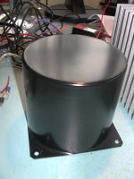
I harvested a power transformer and a few misc other parts from a dead Denon AV receiver that a friend gave me, and I would like to build a simple power amp as project with the neighbor kid (we are presently building a fender champ clone at the moment).
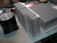
If a suitable project exists with readily available PCBs, that would be ideal. This will hopefully be a "junk box leftovers" kind of project and I have rectifiers, IRF240s, IRF9240's etc left over parts from a Pass F4, mini-A, and F5 as well as a few heatsinks.
So, the transformer is from a Denon AV-1010 receiver with the following specs:
100Wx2 front
35Wx2 center
35Wx2 rear
The measured transformer voltages are:
main stereo 40-0-40 VAC
two other CT leads, 25-0-25 VAC and 18-0-18 VAC
and finally one more set of taps 0-4.5V
All voltages were measured unloaded.
I am assuming that this transformer is really only suitable for an AB amp, and that's fine, as I'd like to use heatsink leftovers that I have.
I'm thinking an AB mosfet based no-feedback amp but I am open to suggestions.
Attachments
This recommendation is down a little different avenue, e.g. no reuse of the parts that you've shown, but perhaps provides an interesting alternative.
Akitika GT-101
Of course, if you have your heart set on the resurrection build, that can be fun too. It's just that the 40-0-40 is a little high for the average chip amp, which would be an easy way to go...
Akitika GT-101
Of course, if you have your heart set on the resurrection build, that can be fun too. It's just that the 40-0-40 is a little high for the average chip amp, which would be an easy way to go...
Some possibilities:main stereo 40-0-40 VAC
two other CT leads, 25-0-25 VAC and 18-0-18 VAC
and finally one more set of taps 0-4.5V
40,0,40vac Honey Badger stereo main channels
40,0,40vac alternative, Honey Badger subwoofer channel (put 220u in for C4)
25,0,25vac BPA300 LM3886, or bridged Honey Badger, or bridged+parallel TDA7293 monophonic subwoofer channel
25,0,25vac alternative, TDA7293 surround channels.
25,0,25vac alternative2, Circlophone or SSA or MyRef-FE main channels.
18,0,18vac LM1875 or TDA7295 surround channels (with tiny input caps and small-ish output caps for ~150hz)
18,0,18vac alternative: 15vdc regulators running a preamp.
4.5vac single, DAC, or led's
4.5vac single, alternative, voltmulti+regulator for remote control kit.
P.S. With 4 bridge rectifiers all yelling at one transformer, I'm assuming that you want RC snubbers per each transformer secondary (if one is expecting hi-fi).
Some possibilities:
40,0,40vac Honey Badger stereo main channels
40,0,40vac alternative, Honey Badger subwoofer channel (put 220u in for C4)
25,0,25vac BPA300 LM3886, or bridged Honey Badger, or bridged+parallel TDA7293 monophonic subwoofer channel
25,0,25vac alternative, TDA7293 surround channels.
25,0,25vac alternative2, Circlophone or SSA or MyRef-FE main channels.
18,0,18vac LM1875 or TDA7295 surround channels (with tiny input caps and small-ish output caps for ~150hz)
18,0,18vac alternative: 15vdc regulators running a preamp.
4.5vac single, DAC, or led's
4.5vac single, alternative, voltmulti+regulator for remote control kit.
P.S. With 4 bridge rectifiers all yelling at one transformer, I'm assuming that you want RC snubbers per each transformer secondary (if one is expecting hi-fi).
How much 40-0-40 VAC current do I need for the Honey Badger? I see this board in the store so that's appealing.....
I like the idea of using the 25-0-25 VAC output for another lower power stereo output......I'll have to research MyRef-FE and TDA7293.
Can you provide more details on the RC snubbers?
I usually hang out in either the tubes forum or the Pass Labs forum so these projects are all rather new to me.
Thanks!
For a stereo pair, approximately 7.5a, but it could run with more or less.How much 40-0-40 VAC current do I need for the Honey Badger? I see this board in the store so that's appealing.....
MyRef-FE has good performance for an LM3886 build and is tuned not to shout, much unlike common gainclone kits. I've made publications for TDA7293 and while the tone is similar, the MyRef's resolution might be higher, but that topic depends on power circuit, mainly.I like the idea of using the 25-0-25 VAC output for another lower power stereo output......I'll have to research MyRef-FE and TDA7293.
Installation: Well, if you don't have a scope handy, try a 2u2 polyester in series to a 50 ohm multi-turn variable resistor to create an adjustable snubber (credits to Keantoken for creating a "kitchen table" method, by request). This RC (a tone control) across transformer's secondaries allows you to muffle the noise, not the audio. The RC is installed directly at the bridge rectifier, for example from the "~" to the "~" of the KBPC1004.Can you provide more details on the RC snubbers?
Compatibility: A power circuit that combines snubbing transformer secondaries with CRC filtering at the power supply is compatible with a wide range of ordinary to botique bridge rectifiers. Snubbing the transformer secondaries has a dual purpose--confine bridge rectifier noise to the bridge rectifier locale, and "waste some noise" into the RC's resistor.
Snubber theory: The cap of an RC snubber prevents wasting good power; however, the resistor of a snubber does the majority of the noise removing task.
Adjustment of the dial may or may not have some of the following:
Clearer and/or higher resolution audio.
A more level sounding (less peakish mids&treble harmonic) response.
A somewhat cooler amplifier heatsink.
*These are practical indications that a noise filter has worked. Scope use would be good; however, the filtering does have some practical benefits that can be used for approximation. If the filter seems non-working, you can change the cap size and re-try. Snubbed transformer secondaries are a normal (and perhaps expected) part of a hi-fi amplifier.
P.S.
If you've done the above first, that filtering has reduced the need of DC side snubbers so that you can use DC side RC cap values so tiny that they could not dull the audio. Yay! It is possible/probable that ordinary CRC power supply would have completed the DC side job and then DC side snubbers aren't required at the power board.
Last edited:
Thanks Daniel, I do have a scope, so how do I dial in the snubber with a scope and func generator?
Are there any lower powered AB projects to recommend with good performance? Say 25-60W or so? We don't need much horsepower.
I also have a few BrianGT PS boards and Peter Daniels PS boards.
Are there any lower powered AB projects to recommend with good performance? Say 25-60W or so? We don't need much horsepower.
I also have a few BrianGT PS boards and Peter Daniels PS boards.
Last edited:
I don't know, but maybe this will help: PRACTICAL SNUBBER AND TERMINATION DESIGNThanks Daniel, I do have a scope, so how do I dial in the snubber with a scope and func generator?
SSA and CirclophoneAre there any lower powered AB projects to recommend with good performance? Say 25-60W or so? We don't need much horsepower.
A parallel LM1875 may also be interesting.
Boywonder, if you can probe the trafo magnetic field with an inductor, or measure the charging currents using a .1R resistor or such, you can tune the snubber by hand while watching the scope. I found the scope was good for finding the general value, but finer tuning should be done by ear near that point. Also try turning the trimmer all the way to 0; that doesn't snub anything but may sound good because of the decoupling effect (I found I preferred the other way though). For a full treatment of trafo resonances more snubbers are needed, but this one will take care of most of the problem. I haven't quite worked out how to adjust the others since it's a nonlinear problem.
I don't know whether the effect of the snubber will be different for toroidal and non-toroidal trafos. Any resonance around the trafo is radiated magnetically, so toroids may not need it as much as EI trafos.
I don't know whether the effect of the snubber will be different for toroidal and non-toroidal trafos. Any resonance around the trafo is radiated magnetically, so toroids may not need it as much as EI trafos.
The reason that I brought it up is that his transformer has a lot of secondary windings and therefore may have a gang of bridge rectifiers all yelling at one transformer. Oh no, a big noise generator! So, I believe that if one wants hi-fi from that system, all of the bridge rectifiers' racket must be confined to the bridge rectifiers' individual locales, in order to Block an each to all pollution situation.
Even after snubbing the secondaries, I'm fairly sure that any small signal purposed DC supply will need high performance K-Multi followed by regulators before it can successfully power high fidelity small signal. For good performance, a discrete "regulated front end" power amplifier (hopefully with paralleled output devices) seems to be the most straightforward solution if one is also preparing to drive modern speakers.
It seems to me that monoblocs with 1 bridge rectifier per 1 transformer might make some matters a bit easier?
How much 40-0-40 VAC current do I need for the Honey Badger? I see this board in the store so that's appealing.....
I like the idea of using the 25-0-25 VAC output for another lower power stereo output......I'll have to research MyRef-FE and TDA7293.
Can you provide more details on the RC snubbers?
I usually hang out in either the tubes forum or the Pass Labs forum so these projects are all rather new to me.
Thanks!
With the 2x25VAC you can build the FetZilla
Everyone: thanks for all of the input!
Lazycat: I checked out the VSSA thread; sounds interesting......I hoping to find a project with PCBs available so I will stay tuned.
Next (dumb) question. Can I estimate the current capability of the 40-0-40 taps with any accuracy by knowing that the AV receiver was rated at 100W output on the main stereo channels? I understand that there is a spectrum of possible class A and AB transition points based on idle current. I would also assume that this operated in vary shallow class A since it was an AV receiver.
Also, if I assume that the 25-0-25 taps were powering the center and rear channels (35W each) can I get a meaningful estimation of current capability for these taps?
Should I just test the transformer under load? I have a few large power resistors but in very limited values.
Can you see and therefore estimate the wire thickness used for each of the 18Vac, 25Vac and 40Vac taps?
Winding wire thickness is a VERY good guide to current rating.
Assume 3.1A/sqmm of cross-section.
All of the wires are Hitachi brand 22awg 105 deg C marked.
Can you see and therefore estimate the wire thickness used for each of the 18Vac, 25Vac and 40Vac taps?
Winding wire thickness is a VERY good guide to current rating.
Assume 3.1A/sqmm of cross-section.
Actually, by measuring the unloaded voltage and the resistance of the winding (short at least one other winding as some multimeters will have a big problem with the inductance of the winding), can give a good estimate of the available current.
Standard EI transformers are wound at up to 10% regulation, which basically means the voltage drop from unloaded to fully loaded is 10%. Using the measured voltage and resitance it's a matter od using ohms law to estimate the available current, and this would be step 1.
Step 2 is adding together voltage x current of all windings to get an estimate of the VA rating of the transformer. This is then compared to the core size. A quick estimate for standard EI cores would be to calculate the cross-section of the central part around which the bobbin is mounted, in square cm. Take 90% of this number and square it, and you get a rough estimate of the VA rating. Divide that with estimate you got from the voltage and resistance measurements, usually this latter will be higher because a rather pessimistic figure was used for regulation, and you will get a figure less than 1, 0.7-0.8 would be quite common. Multiply your estimated winding currents by thet number and you will likely be very close to the actual spec, with some safety margin.
So, here is an example.
Suppose you measure a winding at 40V unloaded. The winding resistance is measured at 1 ohm (remember to subtract the resistance of probe wires which you get by shorting the probes - not the definitive method but a sufficiently precise ballpark value).
Assuming regulation is 10%, this resistance will drop 10% of 40V, i.e. 4V at full load, ohms law tells us this will require 4A of current. So, this winding is capable of sourcing 40V x 4A = 160VA of power. For multiple windings do the calculation for each and add the VA contributions together.
However, measiring the cross section of the iron core inside the bobin gives us say 12 square cm, but since not all of it is iron - there is some insulation and air, assume 90% is iron, and so the actual cross section is 10.8 square cm. THis in turn when squared gives us 10.8 x 10.8 = 116.64VA as the VA rating of the core. Now we divide this with the forst estimate, 160VA and we get 0.729. We use this to multiply our first current estimate to get something closer to the ctual current, in this case it is 4 x 0.729 = 2.916A
This estimate will usually fail for very high current or very low voltage (difficult to measure low resistance of the winding) and very low current (winders will often use thicker wire to make winding easy if this is not the largest power winding on the core) windings in that it may not represent how the transformer was originally designed, but you could still source the calculated current.
(60W*2 for lower ripple)*2 channels=240va. Okay! Right ballpark!boywonder said:Say 25-60W or so? We don't need much horsepower.

Yes, it is possible to get the 60W per channel stereo, in high fidelity. It will have an additional higher capacity of midfi useful for headroom management that sounds better than clipping. If the power supply capacitance is sized big enough to outlast a bass beat yet small&fast enough to recover before the next bass beat, it may do 75 watts per channel if the transformer allows, and also possibly rather large bass peaks that can vary in quality. Surely using the Honey Badger makes a better quality amplifier; however, the Denon's smaller power range behavior persists because of using a lower amperage, mass market retail transformer. This behavior can be quite useful if you have non-gigantic 8 ohm speakers.
Result:
Honey Badger boards with 2x MJL parallel for outputs.
Do C3,C4 as 220u||220u and right size the input cap.
5x6800u per rail simple split rail supply with KBPC3502.
Due to retail transformer, avoid using 4 ohm speakers.
That reads like the leadout wires.All of the wires are Hitachi brand 22awg 105 deg C marked.
It's the wire in the winding you need the thickness of.
Thanks for the replies everyone!
AndrewT: Yes those are the lead wires, I'm not sure I want to dig into the case...
ilimzn: I'm familiar with the concept you've outlined, and used a handy chart published years ago to estimate the current capability of an unknown tube power transformer based on winding resistance. In this case, even with my Fluke 79 meter, it's difficult to measure 1 ohm or less even on the sensitive R range. Tube power transformers at least have resistance that can be measured with a typical meter.
Daniel: So one can scale the number of outputs on the honey badger without much other changes? ie front end stays the same, etc.? This sounds do-able....
Yes, very scalable. The Honey Badger is the result of a modular amplifier system that Ostripper has been designing for some time. It is an advanced version of the AX, part of the Mongrel amp (modular options) series. http://www.diyaudio.com/forums/solid-state/169590-mongrel-supersym-ii.htmlDaniel: So one can scale the number of outputs on the honey badger without much other changes? ie front end stays the same, etc.? This sounds do-able....
Thanks Daniel:
So, what outputs (and how many)?
I'm assuming that running less than 3 pairs at higher bias currents makes more sense than fully populating the outputs and running them with little bias due to transformer current limitations.
I have been searching the various Honey Badger threads about output devices and bias current, but have only found spotty info. I see that most folks are using 600-800VA transformers for this project, and I'm sure the one I have falls far short of that (comparing it to the size of the 400VA Antek 20V transformer in my F4).
I'd be plenty happy with anything between 25-75W or so of output, and happily sacrifice max power out for hotter bias with less/smaller outputs. This project is sort of a "scrap box challenge".
Last edited:
- Status
- This old topic is closed. If you want to reopen this topic, contact a moderator using the "Report Post" button.
- Home
- Amplifiers
- Solid State
- need suggestions for an AB amp project