Hi Guys,
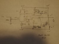
I've been a tube amp fan for the last 25 years trying many, many vintage and DIY amps. Earlier this year I tried a simple Depletion mode MOSFET preamp circuit and liked it a lot. So, I drew up a simple concept amp seen in the attachment. The diff input stage and CCS would be all depletion mode MOSFETs and the output enhancement types.
Since I come from the world of tubes you can see this is very tube like in nature. I don't have the skills to make a fancy direct coupled design so chose capacitors to couple the dif stage to the semi-quasi-complimentery output stage that's fixed bias by CCS fed pots.
I've built the input stage and it works very well by itself with good balance to over 100Khz.
I've yet to build the output and have low cost parts on the way to give it a try.
My main concern isn't so much with higher THD or the coupling caps or even if it'll work but will it blow up on power up? I'm imagening the rapid stabilization of voltages causing big spikes on the output's gates taking them too high. Should I use clamer diodes to be safe or will it blow up anyway?
Thanks,
Scott
Attachments
There are loads of class AB amplifiers around on the internet and on DIYAUDIO.
I would have a look through those.
Most have LTP front end with CCS, into VAS/bias/CCS into output stages.
They aren't too difficult to understand.
One pitfall is making sure the VAS stage doesn't cause oscillation on the output.
This can be fixed with 100-220pf between base and collector of VAS.
I would have a look through those.
Most have LTP front end with CCS, into VAS/bias/CCS into output stages.
They aren't too difficult to understand.
One pitfall is making sure the VAS stage doesn't cause oscillation on the output.
This can be fixed with 100-220pf between base and collector of VAS.
I agree and looked them over as well as the Pass amps. The complete simplicity and tube amp like construction, as well as, scalability of the posted schema is compeling.
Do you think the outputs will blow before the power up voltages get stable? So far there arn't any oscillations on the LTP but it's run without the NFB.
Do you think the outputs will blow before the power up voltages get stable? So far there arn't any oscillations on the LTP but it's run without the NFB.
nice circuit ") I dont see why it would blow up but the zener clamps are probably cheap insurance ... parasitic oscillations can be a bit of a pest sometimes but some small value caps across G-S/G-D or maybe G-G will do the trick if that happens.
I dont see why it would blow up but the zener clamps are probably cheap insurance ... parasitic oscillations can be a bit of a pest sometimes but some small value caps across G-S/G-D or maybe G-G will do the trick if that happens.
Separately, it looks to me that the top and bottom halves would have different gains in the output stage. The top fet will act as a follower with no voltage gain vs the bottom fet which will have voltage gain. I guess feedback + class A might take care of some of the resulting distortion. Good luck and tell us how it goes! Cheers
I dont see why it would blow up but the zener clamps are probably cheap insurance ... parasitic oscillations can be a bit of a pest sometimes but some small value caps across G-S/G-D or maybe G-G will do the trick if that happens.Separately, it looks to me that the top and bottom halves would have different gains in the output stage. The top fet will act as a follower with no voltage gain vs the bottom fet which will have voltage gain. I guess feedback + class A might take care of some of the resulting distortion. Good luck and tell us how it goes! Cheers
- Status
- This old topic is closed. If you want to reopen this topic, contact a moderator using the "Report Post" button.
- Home
- Amplifiers
- Solid State
- Simple all N-channel MOSFET amp