The signal is fed to each of 2 amplifiers' input terminals in reversed phase. The output then, as measured between both positive terminals, is twice that from either single amplifier positive to negative terminal (in normal configuration). That is what "Bridge-Tied Load" means. That is also the same basic scheme for connecting 2 separate mono amplifiers or stereo channels in "bridge-mode" as you see in PA and automotive applications.
Thus you have twice the voltage swing and power for the same supply voltages but you don't have matching increased current capability, so the load impedance rating should be raised from say, 4R minimum to 8R minimum for an equivalent safety margin.
It is a popular means of extending a basic range of amplifier products by just adapting them to BTL connection but the limited current capacity requires better protection and careful planning. It could be said that it is better to use more appropriate designs in the first place.
The bridged amplifiers deliver double the power to the doubled load impedance.
If you sum the total power delivered by each of the amplifiers to it's rated load, you will find that the two amplifiers deliver exactly the same power as the bridged arrangement. NOTHING is gained by bridging.
Two 50W into 4ohms amplifiers deliver 100W into the two 4r0 loads.
A bridged pair of these same amplifiers delivers 100W into 8r0.
Exactly the same power from both arrangements.
There is some cancellation of distortion by bridging. In theory, close to perfect. In reality, closer to nothing.NOTHING is gained by bridging.
Well, no *extra power* is gained, but it can be achieved at a more convenient impedance.NOTHING is gained by bridging
")
That counts as "gaining" in my book.
Besides the classic car audio amps, I can offer another example from the MI world: the excellent Crate Powerblock guitar amp has two 75W/4r amps , which forces you to find two 4 r Guitar speakers (not very common) or carry two 2 x 12" cabinets (bulky) *or* , thanks to bridging, get 150W/8r , which allows you to make a single compact and very loud single 12" cabinet, using, say, an EVM12L or equivalent.
Am I looking at a different image ??
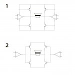
Configuration 1 clearly won't work but I could guess it is suppose to be an "Alexander" type amplifier ?
dc
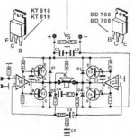
I got from electroschematics. 200W Transistor Audio Amplifier Circuit I don't know if it work or not. I'm still learning about audio amplifier
Attachments
That schematic is correct but difficult to understand unless you know what to look for. Try this:
Google Image Result for http://lenardaudio.com/education/images/a12/a12_bridge-management.gif
Google Image Result for http://lenardaudio.com/education/images/a12/a12_bridge-management.gif
One advantage is that bridged amps can be run direct coupled with
single PS voltage. One of the reasons it is so common in car amps.
Hi,
And its most common application by far. A lot more power
from a single DC supply and no output coupling capacitors.
For car audio it has overwhelming advantages.
rgds, sreten.
Sorry but that bridged TDA2030 amp, as shown, will be very happy to supply 50W RMS and that with a very stiff PSU.
120W? Not in your dreams.
*Maybe* it could come close with a 2 ohm speaker, but since by now you are needing 2 power chips + 4 power transistors (25A , 125W each), you might either go discrete or bridge a couple of the larger 60/80W chipamps.
Funny thin is, this same circuit is posted all over the net as a "200W" amplifier, go figure.
Mind you, it *does* work, only it supplies far less power than that.
A customer of mine made quite a few $$$$ selling crummy "200W Powered Speakers" around this power module, a fake "horn+driver" (a homemade plastic horn with a Piezo cone and crystal glued to the throat, no phase compensation or anything else) + the cheapest lightest 15" speaker I could make.
I made one as a joke, using a cookie sized magnet .... and he ordered 100 !!!
Best (worst?) is that he sold all of them real quick
Must recognize that the completed powered cabinet ***looked*** impressive.
That schematic is correct but difficult to understand unless you know what to look for. Try this:
Google Image Result for http://lenardaudio.com/education/images/a12/a12_bridge-management.gif
With the base shorted to the emitter ?
A new one on me
I think ian finch, in post#10, clearly is speaking about the image in post#9 .... which is small but correct.
*Maybe* you refer to the very poor image in post #1, which by then was old news.
And in fact the other example there does not work either, but I consider them closer to "block diagrams" than actual schematics.
*Maybe* you refer to the very poor image in post #1, which by then was old news.
And in fact the other example there does not work either, but I consider them closer to "block diagrams" than actual schematics.
- Status
- This old topic is closed. If you want to reopen this topic, contact a moderator using the "Report Post" button.
- Home
- Amplifiers
- Solid State
- [Ask] Bridge amplier topology