Hi ,
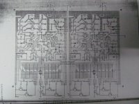
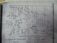
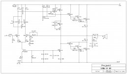
This schematic along with PCB and construction guide was published in EFY magazine about 25 yrs ago (when I was born)") . It was rated or advertised at 120W@4ohms .I was looking into my old stuff when i found the PCB and schematic. I made this amplifier about 8-9 yrs ago when I was in school and amazingly IT Worked for about an hour or so till the outputs and drivers burned out(i used 2n3773 and tip122 maybe). I remember it was my fault, as I used tiny heat sinks and didn't know how to set bias and other things. I abandoned this project and made a nice and working STK465 amp, using its power supply and transformer(30-0-30V,8A).
. It was rated or advertised at 120W@4ohms .I was looking into my old stuff when i found the PCB and schematic. I made this amplifier about 8-9 yrs ago when I was in school and amazingly IT Worked for about an hour or so till the outputs and drivers burned out(i used 2n3773 and tip122 maybe). I remember it was my fault, as I used tiny heat sinks and didn't know how to set bias and other things. I abandoned this project and made a nice and working STK465 amp, using its power supply and transformer(30-0-30V,8A).
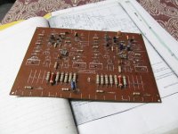
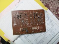
As i found the PCB and got some 2n3773's, ttc5200's, 2sc4793,sa1837, tip41,42c and bd139,40's I am looking forward to rebuild this amp.
Any advice and if anybody know this amp are welcome.
Regards,
Aniket
This schematic along with PCB and construction guide was published in EFY magazine about 25 yrs ago (when I was born)
. It was rated or advertised at 120W@4ohms .I was looking into my old stuff when i found the PCB and schematic. I made this amplifier about 8-9 yrs ago when I was in school and amazingly IT Worked for about an hour or so till the outputs and drivers burned out(i used 2n3773 and tip122 maybe). I remember it was my fault, as I used tiny heat sinks and didn't know how to set bias and other things. I abandoned this project and made a nice and working STK465 amp, using its power supply and transformer(30-0-30V,8A).As i found the PCB and got some 2n3773's, ttc5200's, 2sc4793,sa1837, tip41,42c and bd139,40's I am looking forward to rebuild this amp.
Any advice and if anybody know this amp are welcome.
Regards,
Aniket
Attachments
Hi Andrew,
Have you build this amp? How was your experience?
I was thinking to rebuild this amp with modern components as I have some to spare and I also have the PCB and it did worked when i first made it.
If you tell me something more about it then i would think again to rebuild this amp.
Regards,
Aniket
Have you build this amp? How was your experience?
I was thinking to rebuild this amp with modern components as I have some to spare and I also have the PCB and it did worked when i first made it.
If you tell me something more about it then i would think again to rebuild this amp.
Regards,
Aniket
one option might be to convert it to a complementary amplifier since this one is a quasi ( all outputs NPN )
In case you decide to built it any way and either way quasi or not you need to find a way to attach TR 7 to the main heatsink so it is possible to sense temperature and adjust bias accordingly ( very critical for thermal stability) TR7 can also be replaced with a BD 135-139 for easy mounting .
In case you decide to built it any way and either way quasi or not you need to find a way to attach TR 7 to the main heatsink so it is possible to sense temperature and adjust bias accordingly ( very critical for thermal stability) TR7 can also be replaced with a BD 135-139 for easy mounting .
Hi Aniket,
You have most important part of the DIY amplifier, PCB is there and its partially populated. I would suggest you go ahead and replace the bad components with proper heat sinks and power it up with standard DIY amp procedure. Once it works as expected, if you want to improvise the sound you can replace some of the transistors with advanced ones. But for now complete as it is, I guess this should be a good amplifier.
Thanks,
I propose you keep this design too, but replace with newer parts. If you want to try something little different, try amp from this thread http://www.diyaudio.com/forums/solid-state/88258-brother-quasi.html ,your PCB's will fit with minor changes.
Best regards
Best regards
Thanks all,
Any advice for substitutes, as none of the transistors are available except bd139,140.
As i figured out for bc147-bc547c, cil603,612-bc546b, 2n6254-2n3773 and 2n6261-tip41c should do.
For complementary design i need to cut the traces on the PCB and i might use 2 pairs of output devices, and i have some ttc5200 and tta1943 for complementary pair.
Regards,
Aniket
Hi Aniket
greetings many better designs are on this forum with easy to get parts
more power and better sonics just finishing a amp for my friends we have a small band
this amp sound quality and power output is better than all indian amps and most chinese amps so go through the forums and decide which amp fits your bill money wiseand availabilty of components
warm regards
andrew lebon
Hi Andrew,
I am rebuilding this amp only for learning purpose. As i have the PCB i would just mount the components and suitable transistors, if it works then great, if it doesn't no matter, would just give it a try and which amp you are referring/making?
Of course there are great designs in the forum, Apex B500, AX14/20, SR100/200 and DX's Blame ST and MKIII and DIY AB amp(the Honey Badger) and I follow these threads, for sure I would build one of these amps later for my home system.
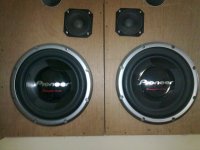
Currently i am using the amp(schematic attached), i made myself and i m very happy with its performance and sound quality, with the speakers i use(image attached), it shakes my apartment and has earthquake like bass.
Regards,
Aniket
I am rebuilding this amp only for learning purpose. As i have the PCB i would just mount the components and suitable transistors, if it works then great, if it doesn't no matter, would just give it a try and which amp you are referring/making?
Of course there are great designs in the forum, Apex B500, AX14/20, SR100/200 and DX's Blame ST and MKIII and DIY AB amp(the Honey Badger) and I follow these threads, for sure I would build one of these amps later for my home system.
Currently i am using the amp(schematic attached), i made myself and i m very happy with its performance and sound quality, with the speakers i use(image attached), it shakes my apartment and has earthquake like bass.
Regards,
Aniket
Attachments
Success!!
The amp worked fantastic. Using ordinary components and minor changes in the bias circuit it sounded quite nice.
I used BC547,BC546 for the input stage and BD139,140 for VAS and pre driver and TIP41C as driver and a quasi output stage with 2N3773. Set the bias at 75mA. The amp was so stable and quite and the heat sink was just warm after 2 hrs. continuous playing loud. I used an 8" 60W 4ohm woofer for testing and a basic +/-16 V supply for testing. I was wondering how it played so loud and clear with only 16 volts, amazed. Have a look at the video.https://www.youtube.com/watch?v=-zv_k7KH1eM
Nice job and good sound too.The power is a about 10w, don't expect much heat.Ur heatsink is big enough for 2x100w amp without force cooling. You use triple output stage, like original schematic, right? And please, can you redraw actual schematic with modifications u made.
Last edited:
I am redrawing the schematic with the changes I made. I got some mje15032/33. So, I would try a full complementary TEF design with ttc5200/1943 outputs, mje15032/33 as drivers and bd139/140 as predrivers. I hope it would sound better, using the power transformer suggested in the original schematic(33-0-33V, 10A). Would post soon..
Regards,
Aniket
Regards,
Aniket
Yes, all trannies you mentioned are amongst best for audio in specific parts -bd139-140 for VAS and VBE multiplier, mje15032-33 for driver and 2sc5200, 2sa1943 for final stage, but if you go over 42v dc powersupply, I recommend mje/kse340-350 for VAS. Thanks in advance for schematic.
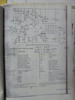
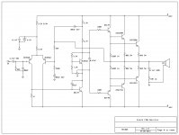
Schematic with Complementary Outputs
Proposed schematic, would need to cut some traces on the PCB for complementary design. I would rather use a 35-0-35 transformer to get +/-50V as there's hardly any difference with 33-0-33(as recommended in the orig. schematic) vs 35-0-35, 10A. Would post the results soon.
Regards,
Aniket
Proposed schematic, would need to cut some traces on the PCB for complementary design. I would rather use a 35-0-35 transformer to get +/-50V as there's hardly any difference with 33-0-33(as recommended in the orig. schematic) vs 35-0-35, 10A. Would post the results soon.
Regards,
Aniket
Attachments
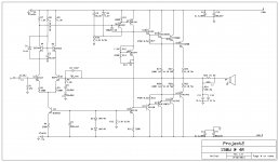
hiProposed schematic, would need to cut some traces on the PCB for complementary design. I would rather use a 35-0-35 transformer to get +/-50V as there's hardly any difference with 33-0-33(as recommended in the orig. schematic) vs 35-0-35, 10A. Would post the results soon.
Regards,
Aniket
can i use this amp for 2 OHM speaker with TIP41-42C ?
can you please share PCB ?
i need 100W power
thanks
hi
can i use this amp for 2 OHM speaker with TIP41-42C ?
can you please share PCB ?
i need 100W power
thanks
Hi Hadighorbani,
See post#1
As this amp is 25 yrs old there's no PCB file. But there's a pic of the PCB. You could design your own PCB. Schematic is there. But i have not tested this amp at full voltage. Only used +/- 16V and it worked fine with a 4 ohm load.
Regards,
Aniket
Amp tested @ +/- 42V
Amp rocks on +/-42 V rails. i used 2 pairs ttc5200/1943 outputs. bias set at 35mA per pair, got just 0.8V DC offset. Bass is tight and deep, crystal clear highs.
I got a bunch of 0.1R 5W resistors, so i matched and used them instead of 0.22R as emitter resistors. Amp is stable at 4ohm load with heatsink not more than warm after 1.5 hrs of loud music.
Also i simulated it in multisim and surprisingly simulation results are very close to the actual working circuit, how precise multisim is... great!!!. With only minor differences simulation results show 0.08V DC offset as compared to 0.8V for the working circuit. THD figures are 0.056%@20kHz-130W@4ohm. with mjl21193/4 output transistors.
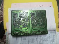
As i have the PCB already now I need good casing, heatsinks and a good power supply. I would increase the rails to +/-56V with a 40-0-40, 12A transformer and use 4 output pairs per channel with mje15032/33 as drivers and mje340/350 or 2sc4793/1837 as predrivers. Already started collecting parts,
would post pics of the complete amp soon.
Thanks and Regards,
Aniket
Amp rocks on +/-42 V rails. i used 2 pairs ttc5200/1943 outputs. bias set at 35mA per pair, got just 0.8V DC offset. Bass is tight and deep, crystal clear highs.
I got a bunch of 0.1R 5W resistors, so i matched and used them instead of 0.22R as emitter resistors. Amp is stable at 4ohm load with heatsink not more than warm after 1.5 hrs of loud music.
Also i simulated it in multisim and surprisingly simulation results are very close to the actual working circuit, how precise multisim is... great!!!. With only minor differences simulation results show 0.08V DC offset as compared to 0.8V for the working circuit. THD figures are 0.056%@20kHz-130W@4ohm. with mjl21193/4 output transistors.
As i have the PCB already now I need good casing, heatsinks and a good power supply. I would increase the rails to +/-56V with a 40-0-40, 12A transformer and use 4 output pairs per channel with mje15032/33 as drivers and mje340/350 or 2sc4793/1837 as predrivers. Already started collecting parts,
would post pics of the complete amp soon.
Thanks and Regards,
Aniket
Attachments
- Status
- This old topic is closed. If you want to reopen this topic, contact a moderator using the "Report Post" button.
- Home
- Amplifiers
- Solid State
- Anybody know this Amp