is probably the sound of the transformer, the best you can raise to the heavens of Music
you will say that is not new
In fact, there is no tone mark
here is a good example of an application
without special components
you can test the validity of the argument by placing a normal amplifier with unity gain
thus eliminating the resistance of the inverting input which is connected to ground
you will say that is not new
In fact, there is no tone mark
here is a good example of an application
without special components
you can test the validity of the argument by placing a normal amplifier with unity gain
thus eliminating the resistance of the inverting input which is connected to ground
Attachments
Last edited:
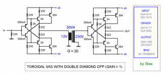
a transformer as an amplifier
I kind of agree. I like the transformer as a gain device.
Only thing to argue may be the implementation

See Susan Parker's Zeus power amp:
Zero Feedback Transformer Audio Power Amplifier
Zero Feedback Transformer Audio Power Amplifier
See Susan Parker's Zeus power amp:
Zero Feedback Transformer Audio Power Amplifier
I think it is a bad idea put the transformer at the output. The current through the transformer should be minimised, not maximised as happends at the output.
Better to use transformer as small signal voltage gain stage at the input and use electronic current buffer at the output.
- Elias
I think it is a bad idea put the transformer at the output. The current through the transformer should be minimised, not maximised as happens at the output.
Better to use transformer as small signal voltage gain stage at the input and use electronic current buffer at the output.
- Elias
Given the sophistication of your analysis techniques for speakers on your home page I am surprised at the above statement since all speaker driver units are transformers.
Electric Flux <<->> Acoustic Vibration
Or perhaps I am missing something here?
Best,
Susan.
Thank you for the kind words regarding my home page
There is however one distinct difference between a transformer in question here and a drive unit: saturating core. High energy signals are poison for the core magnetism. For me it is counter productive to put a transformer at the position of the highest energy in the signal chain. I would rather use a transformer in earlier stages at lower energy levels.
Maybe you have pondered the option too, using only input transformer as a voltage gain stage and e.g. a source follower for output buffer driving the speaker ?
As a side note, I think it is magnetic flux, not electric, causing cone vibration in a moving coil speaker, or maybe you are talking about ESL.
- Elias
Given the sophistication of your analysis techniques for speakers on your home page I am surprised at the above statement since all speaker driver units are transformers.
Electric Flux <<->> Acoustic Vibration
Or perhaps I am missing something here?
Best,
Susan.
Hi Elias,
I bias my transformers at up to 1.5 amps, and would go higher for the full range SE version.
For SE I have a suitable gap using copper shim. For PP the use of EI laminations automatically gives a small gap, which I have found to be good enough for a few mA imbalance that I typically end up with after matching mosfet pairs.
I have on my bench at present a EI120 SE output transformer that is biased at 1.5 amps and has a 1.0mm gap (so total gap in magnetic path is 2.0mm).
This is destined for operating at 1KHz and above in a bi-amp system with a PP output stage for the LF part. Passive 600 ohm impedance crossover between the line driver and the power stages.
So the SE transformer as above is running at about 450 Ampere Turns bias with a 300 turn 1.0 mm wire primary.
Measured -3dB points = 8.3Hz & 177kHz @ 1 Watt into 8 ohms, with 0.026% THD @ 1kHz (2nd harmonic @ -74dB and 3rd harmonic @ -80dB to the fundamental).
Since this transformer is destined for a HF stage I can increase the gap (which reduces the inductance) and push the high end -3dB point up to around 1 MHz.
At the moment with a 31 Volt supply I get a bit over 10 Watts into 8 ohms.
Lots of people tell me to "improve" my design by getting rid of the output transformer. But the use of transformers is the whole point of my design, so why would I do that?
I can do a whole line level amplifier with seven primary components; four transformers and three mosfets (each mosfet has a protection zener, and a gate resistor), and two impedance termination resistors.
Obviously I am not including connectors, switches and power supplies in this... all of which can in their own right degrade the audio quality.
The magnetic field is caused by electrons flowing in a wire i.e. a current flow. Easily demonstrated by taking a horseshoe magnet, dangling a bit of wire across the gap between the poles (wire should have some flex in it) and chucking a few amps through it from a current limiting power supply.
In the case of a loudspeaker the a/c current flow in the voice coil causes a magnetic field that intersects the static magnetic field of the driver's magent in the gap between the poles and causes cone movements. It should be noted that as forces attract and repel even the nominal permanent filed of the driver is modulated in intensity by the field that is cutting it. Hence the whole Alnico versus Rare Earth debate. The different field strengths and how they react is (apparently) audible to those sensitised to the effects.
===
I appreciate that you comment "High energy signals are poison for the core magnetism" obviously has some founding in your personal experience but perhaps you can put some numbers to that?
Best wishes,
Susan.
Thank you for the kind words regarding my home page
There is however one distinct difference between a transformer in question here and a drive unit: saturating core. High energy signals are poison for the core magnetism. For me it is counter productive to put a transformer at the position of the highest energy in the signal chain. I would rather use a transformer in earlier stages at lower energy levels.
I bias my transformers at up to 1.5 amps, and would go higher for the full range SE version.
For SE I have a suitable gap using copper shim. For PP the use of EI laminations automatically gives a small gap, which I have found to be good enough for a few mA imbalance that I typically end up with after matching mosfet pairs.
I have on my bench at present a EI120 SE output transformer that is biased at 1.5 amps and has a 1.0mm gap (so total gap in magnetic path is 2.0mm).
This is destined for operating at 1KHz and above in a bi-amp system with a PP output stage for the LF part. Passive 600 ohm impedance crossover between the line driver and the power stages.
So the SE transformer as above is running at about 450 Ampere Turns bias with a 300 turn 1.0 mm wire primary.
Measured -3dB points = 8.3Hz & 177kHz @ 1 Watt into 8 ohms, with 0.026% THD @ 1kHz (2nd harmonic @ -74dB and 3rd harmonic @ -80dB to the fundamental).
Since this transformer is destined for a HF stage I can increase the gap (which reduces the inductance) and push the high end -3dB point up to around 1 MHz.
At the moment with a 31 Volt supply I get a bit over 10 Watts into 8 ohms.
Maybe you have pondered the option too, using only input transformer as a voltage gain stage and e.g. a source follower for output buffer driving the speaker ?
Lots of people tell me to "improve" my design by getting rid of the output transformer. But the use of transformers is the whole point of my design, so why would I do that?
I can do a whole line level amplifier with seven primary components; four transformers and three mosfets (each mosfet has a protection zener, and a gate resistor), and two impedance termination resistors.
Obviously I am not including connectors, switches and power supplies in this... all of which can in their own right degrade the audio quality.
As a side note, I think it is magnetic flux, not electric, causing cone vibration in a moving coil speaker, or maybe you are talking about ESL.
The magnetic field is caused by electrons flowing in a wire i.e. a current flow. Easily demonstrated by taking a horseshoe magnet, dangling a bit of wire across the gap between the poles (wire should have some flex in it) and chucking a few amps through it from a current limiting power supply.
In the case of a loudspeaker the a/c current flow in the voice coil causes a magnetic field that intersects the static magnetic field of the driver's magent in the gap between the poles and causes cone movements. It should be noted that as forces attract and repel even the nominal permanent filed of the driver is modulated in intensity by the field that is cutting it. Hence the whole Alnico versus Rare Earth debate. The different field strengths and how they react is (apparently) audible to those sensitised to the effects.
===
I appreciate that you comment "High energy signals are poison for the core magnetism" obviously has some founding in your personal experience but perhaps you can put some numbers to that?
Best wishes,
Susan.
@ 1 Watt into 8 ohms, with 0.026% THD @ 1kHz (2nd harmonic @ -74dB and 3rd harmonic @ -80dB to the fundamental).
I see you measure all the nonlinear responses at 1kHz or higher. How about at 20Hz at full power ? Seldomly high freqs are problem for a transformer in terms of nonlinearities.
Another issue is I see you use steady state measurement for distortion.
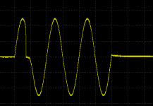
In reality the transformer distortion is heavily time dependent i.e. it has strong memory effects.
For example, here I measured a transformer with 3 cycle sinusoidal at 50Hz. It can be seen the first half of the cycle is badly distorted but all the following half cycles are not so much distorted. If you try to catch this type of distortion using steady state analysis like log sweep, it will fail to show it.
At the moment I'm about to develope a wavelet based nonlinear measurement method to be able to characterise nonlinearities with memory better than steady state methods do.
- Elias
Attachments
Something worth reading:
The handout of the tutorial "Hot and Nonlinear - Loudspeakers at High Amplitudes" by Wolfgang Klippel
http://www.klippel.de/uploads/media/Klippel_Tutorial_Hot_and_Nonlinear_2011.pdf
Best,
Susan.
The handout of the tutorial "Hot and Nonlinear - Loudspeakers at High Amplitudes" by Wolfgang Klippel
http://www.klippel.de/uploads/media/Klippel_Tutorial_Hot_and_Nonlinear_2011.pdf
Best,
Susan.
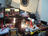
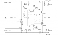
Stee has inspired me to pull out some old ideas from several years back involving the common automobile low voltage incandescent light bulb, in which I built an amp with two Wagner 1004 bulbs in parallel as the collector load of a 2N3055 transistor, working at 12 VDC. Stee brings up transformer coupled solid state amps and CFP stages. These ideas led me to put together a small SE amp which may not look like much on paper, but does sound very nice with a good low end, and incorporates these ideas. The scheme and a photo of the "chaotic desk" where the amp is playing some Sinatra is found below. With these lamps you just about need to wear shades, but that's OK when Coltrane is playing.
The bias is adjusted for half Vcc at the midpoint, which ends up approx 900 mA or so. The amp usually starts out at about 9 volts midpoint rising to and settling in at approx 12 volts in about 5 minutes. The Triad N-1X autoformer is interesting, as it provides an odd mix of both voltage gain, stepped down, and current drive for the output BJT. This is a common 230/ 115 VAC autotransformer. It has an overall DCR of 41.5 ohms, and has almost 100 mA flowing through it from the CFP. This utilizes the DCR to establish 4 volts across the "primary" and yields 2 volts at the center tap for output BJT bias. I yanked the pot in favor of a 120 ohm resistor, and the .33 uF compensation cap is not strictly necessary, but I like it in there. I emailed the engineers at Triad and asked if this were a gapped core former, as visual inspection looked like it could be, and because saturation does not seem to be an issue here----but they did not see fit to reply, must have thought it was some flake asking that Oh well, Thanks Stee! and thanks to Ms. Parker for the interesting information.
Best,
Terry
The bias is adjusted for half Vcc at the midpoint, which ends up approx 900 mA or so. The amp usually starts out at about 9 volts midpoint rising to and settling in at approx 12 volts in about 5 minutes. The Triad N-1X autoformer is interesting, as it provides an odd mix of both voltage gain, stepped down, and current drive for the output BJT. This is a common 230/ 115 VAC autotransformer. It has an overall DCR of 41.5 ohms, and has almost 100 mA flowing through it from the CFP. This utilizes the DCR to establish 4 volts across the "primary" and yields 2 volts at the center tap for output BJT bias. I yanked the pot in favor of a 120 ohm resistor, and the .33 uF compensation cap is not strictly necessary, but I like it in there. I emailed the engineers at Triad and asked if this were a gapped core former, as visual inspection looked like it could be, and because saturation does not seem to be an issue here----but they did not see fit to reply, must have thought it was some flake asking that
Oh well, Thanks Stee! and thanks to Ms. Parker for the interesting information.Best,
Terry
Attachments
Triad autoformer
Hi Terry,
I don't have any experience with these, it's possible that the construction is all Es and all Is just all together in a bunch rather than interleaved as this saves considerably on manufacturing overhead. Typically they might be welded on the seam, but would need to remove clamp to see.
It always nice to see how judicious use of a transformer or inductor can be put to good use in an amplifier.
Best wishes,
Susan.
Hi Terry,
I emailed the engineers at Triad and asked if this were a gapped core former, as visual inspection looked like it could be, and because saturation does not seem to be an issue here----
I don't have any experience with these, it's possible that the construction is all Es and all Is just all together in a bunch rather than interleaved as this saves considerably on manufacturing overhead. Typically they might be welded on the seam, but would need to remove clamp to see.
It always nice to see how judicious use of a transformer or inductor can be put to good use in an amplifier.
Best wishes,
Susan.
Thank you very much Susan!
I bought the autoformer to use as it was intended, then somehow got involved with this application. (Blame Stee). These autoformers are most efficient devices, and this Triad unit can be bought for something like $13 to $14 at Newark Electronics. Not nearly as refined as the transformers you use, but sufficient for the task. I hate to have to pull the casing off, but might have to do it to check the core--just to satisfy curiosity. I could measure the inductance out of circuit, but it does me little good as I would have no idea what the actual incremental inductance would be with 100 mA flowing. Thanks again.
Best,
Terry
I thought of building a Zeus amp with a transformer from a 100V amplifier (with 16,8,4ohm and 50V, 70V, 100V taps) 50V being separate winding it seems.
It also had a drive transformer with two secondery windings instead of a center tapped and I thought of matching bias current by pot rather than matching transistors exactly.
However I halted the project after reading this article as subwoofer amp was the goal.
High Voltage Audio
Elias lifts some concern of low frequency distortion as well, how bad or well would a transformer work for sub duty?
I already use a small toroid (115V to 30V 400Hz 4VA) to minimize class D/amp noise to my 110dB compression drivers so I know HF works well.
I was too hasty and owe Triad an apology
Triad did see fit to reply. Thanks to Jim and Bill at Triad.....here's their reply:
Hello Terry,
Our N-1X does not have a “gapped” core; although it was not designed around a DC bias current, obviously the core perm, flux density, and core structure allow for your use. Since it is designed for 230V input (I am assuming) your considerably lower audio signal will allow the core to handle the DC bias current.
Kind regards,
Jim Mettler
Engineering Manager
Triad Magnetics
22520-B Temescal Canyon Road
Corona, CA 92883
I emailed the engineers at Triad and asked if this were a gapped core former, as visual inspection looked like it could be, and because saturation does not seem to be an issue here----but they did not see fit to reply
Triad did see fit to reply. Thanks to Jim and Bill at Triad.....here's their reply:
Hello Terry,
Our N-1X does not have a “gapped” core; although it was not designed around a DC bias current, obviously the core perm, flux density, and core structure allow for your use. Since it is designed for 230V input (I am assuming) your considerably lower audio signal will allow the core to handle the DC bias current.
Kind regards,
Jim Mettler
Engineering Manager
Triad Magnetics
22520-B Temescal Canyon Road
Corona, CA 92883
- Status
- This old topic is closed. If you want to reopen this topic, contact a moderator using the "Report Post" button.
- Home
- Amplifiers
- Solid State
- a transformer as an amplifier