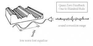
I have invented a method to sound the amplifier in the solid state as a valvular, so reduce to a minimum the negative feedback with a rule called 1:100 ")
Take a simple amp
Ie without cascode in the input stage, without cascode stage voltage and with unity gain in the output stage (without Darlington)
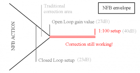
The open-loop gain will be approximately 27dB
Set the closed-loop gain to a gain much greater 40dB
(set NFB resistor's ratio one to hundred)
This means doing the opposite of the traditional approach
You will get a sound but not distorted, but no EQ
This is because there is no longer a residual gain sufficient to correct the waveforms extensive (low frequency)
In short you are listening to the real sound of your amp
And you realize that the impedance matching the speaker load is scarce
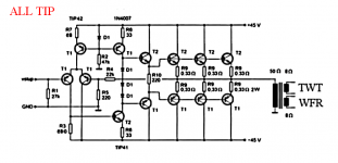
My solution is to adopt an output transformer more powerful than that required
With very low transformation ratio (7:1)
So as not to inflict emphasis on the acoustic scene and at the same time allow the device to an internal resistance adequate
The result is excellent (tested on diagram Rotel RA-02 with toroidal transformer 230/32 +32 V 300VA)
http://www.esafono.it/Esoter Evoque Pure Amplifier.pdf
Take a simple amp
Ie without cascode in the input stage, without cascode stage voltage and with unity gain in the output stage (without Darlington)
The open-loop gain will be approximately 27dB
Set the closed-loop gain to a gain much greater 40dB
(set NFB resistor's ratio one to hundred)
This means doing the opposite of the traditional approach
You will get a sound but not distorted, but no EQ
This is because there is no longer a residual gain sufficient to correct the waveforms extensive (low frequency)
In short you are listening to the real sound of your amp
And you realize that the impedance matching the speaker load is scarce
My solution is to adopt an output transformer more powerful than that required
With very low transformation ratio (7:1)
So as not to inflict emphasis on the acoustic scene and at the same time allow the device to an internal resistance adequate
The result is excellent (tested on diagram Rotel RA-02 with toroidal transformer 230/32 +32 V 300VA)
http://www.esafono.it/Esoter Evoque Pure Amplifier.pdf
Attachments
Last edited:
Stee,
The feedback factor is the difference between open loop and closed loop gain.
If you wish to lower the feedback factor so that you can listen to the amp non-linearity better, you can just lower the open loop gain and save the cost of the xformer.
Loading T1 collector would be a convenient place.
You coulkd even put a pot there for continuous control of open loop gain and feedback factor.
jan
closed loop gain
If you wish to lower the feedback factor so that you can listen to the amp non-linearity better because lose equalization
the attenuation factor of the feedback(and viceversa the correction factor) does not behave as you think
is difficult to set a dime with potentiometer - better to add a resistor in parallel
Attachments
Last edited:
Thanks
I speak about equalization because the negative feedback is a system of dynamic attenuation
This system attempts (up where he space of action) to correct the deficiency by the load current increasing the voltage
This happens on the frequencies of large amplitude that the bass
where there is no output stage is really capable (large parallel end devices es.TIP35)
Goat, I believe you are wrong. The anode of the led is wired to GND via a 22K resistor, and the cathode to -42V, so it really has about 20 mAcurrent in it.
Although, I can´t understand how this circuit warranties or ensures an idle output voltage less than the famous 25 milliVDC though the load, and prevents temperature drift of this output voltage. (???)
Although, I can´t understand how this circuit warranties or ensures an idle output voltage less than the famous 25 milliVDC though the load, and prevents temperature drift of this output voltage. (???)
Stee...
Ummm... hate to call it what it is, but "********", brother.
The "Quasi-zero feedback amplifier" in the original PDF cannot work. It has at least 4 design errors. One is significant enough to prevent operation of the long-tailed differential pair up front, completely.
Specifically, the resistor R8 is connected to ground, which prevents the current source Q1 from conduction, at all. The LED will never light, as there is no V+ path to it. Now... go find the other 3 errors ... they're not as significant, but just as important.
GoatGuy
Please point out the other 3 errors on this proven design.
300/500W Subwoofer Power Amplifier
Last edited:
the attenuation factor of the feedback(and vice versa
the correction factor) does not behave as you think
Hi,
It doesn't work the way you think either, your just making up
how it "allegedly works" and ignoring basic feedback theory.
rgds, sreten.
Hi,
I'm not interested in proposals with no theoretical backing.
Or what people who might actually do it would say about it.
There nothing new under the sun in basic feedback theory
and there hasn't been for a long time. This is just some
made up "rule of thumb" of no real practical significance.
rgds, sreten.
Dear Stee, I understand what you are trying to say, but there's some problem, at least on the amp example you show in post #1.
That amp main gain block, T2, has *at least* 50 to even 60 dB gain, and probably much more.
In Lin type amps such as this one, it can surpass 60dB, I calculated "worst case" to get more in line with your theory but even so we still have too much open loop gain.
*There are* amps designed with much lower open loop gain, and even meant to be used with no NFB at all, you'll find many examples, even in DIYaudio itself.
If interested, search around.
As of the output transformer, it's used *after* the output signal is "already made" by the power amplifier, all it does is lower its RMS power by a factor of 6, and the available output voltage by a factor of 2.5 .
It's not involved in NFB or gain at all, it's an external pasive element.
You show separate 8 ohms windings for Tweeter and Woofer, do you intend to connect them straight there, without a crossover or something?
Thanks.
Ps: all this written with the utmost respect, and doubly so because for an Argentine the Caniggia surname is sort of heroic
- Status
- This old topic is closed. If you want to reopen this topic, contact a moderator using the "Report Post" button.
- Home
- Amplifiers
- Solid State
- solid state with output transformer