I purchased a Panasonic surround system some time ago, without the controller module ie: DVD player etc, and just ended up with the Subwoofer and 5.1 surround speakers. I need to identify the connections on the plug that goes to the subwoofer and main amp, which supplies output to the speakers, .... SO that the output connections of a surround soundcard can interface with the input plug on the Subwoofer/Amp .... (CN501)
If someone with knowhow in this area can let me know what the connections are and mean and what to connect them to and what not to (or what is not necassary) that would be super gr8 !!
The connector code on the schematic is: CN501, and I need to get the 5.1 speakers connected, as well as the blue led 'on' light and remote switch 'on' and a mute button.
If anyone can help it would be much appreciated. I have had this sitting around for about 2 years new and not connected. I need to connect it to my new PC.
From what I can see on the schematic:
1.(1,25) "AC1" + (3,23) "AC2" must be + voltage;
2....while (9,10,13,16,18) "A GND" x 4 must be - voltage. (all are connected)
3....yet --- (6) "D GND" is not part of the 'ground connected hub'.
4.(7,22,24) "FL" must be 'front left'
5.(11) "FR" must be 'front right
6.(12) "SL" must be 'surround left'
7.(14) "SR" must be 'surround right"
8.(15) "C" must be 'centre'
9.(17) "SW" must be 'subwoofer'
10.(20) "mute av centre surround sync" appears to be some kind of 'mute surround' feature leaving only stereo?
I have no idea what:
■(2) "DC DET" is for ?
■(4) "8Y86V" is for?
■(5) "HP CNT" is for?
■(6) "D GND" is for?
■(8) "HELP" is for?
■(19) "PC CONT" is for?
(one must be for the 'on' led light ie: '8Y86V + D-GND?)
...if anyone can help would be appreciated...
I have attached the schematic: Thanks....
Attachments
I have bought the same unit without controller or dvd player. I wast paying much attention on those voltages, they are probably for turning on and off and muting.
The first I did was removing all that digital on off switch thing in front transformer and connected it directly on ac, with analog switch of course")
I have tested the pins and all the channels are working. But all are working full range, the crossover is in main unit so you will need to make one or not if you are connecting it to a computer with 5.1 output.
Mine is going to be connected with active crossover.
The first I did was removing all that digital on off switch thing in front transformer and connected it directly on ac, with analog switch of course
I have tested the pins and all the channels are working. But all are working full range, the crossover is in main unit so you will need to make one or not if you are connecting it to a computer with 5.1 output.
Mine is going to be connected with active crossover.
I have bought the same unit without controller or dvd player. I wast paying much attention on those voltages, they are probably for turning on and off and muting.
The first I did was removing all that digital on off switch thing in front transformer and connected it directly on ac, with analog switch of course
I have tested the pins and all the channels are working. But all are working full range, the crossover is in main unit so you will need to make one or not if you are connecting it to a computer with 5.1 output.
Mine is going to be connected with active crossover.
Thanks...
So exactly which of the 25 pins on the connector did you connect; and to where?
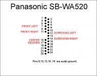
Here are the pins labeled.
The picture here is when you look from the back side. You can see print of a small "1" and "25". And you count pins according to a picture. I did not solder wires on pins because they are too close. I traced the lines to find the first pin of a 100 ohm resistor before input so I can have much more room for soldering.
The picture here is when you look from the back side. You can see print of a small "1" and "25". And you count pins according to a picture. I did not solder wires on pins because they are too close. I traced the lines to find the first pin of a 100 ohm resistor before input so I can have much more room for soldering.
Attachments
Here are the pins labeled.
The picture here is when you look from the back side. You can see print of a small "1" and "25". And you count pins according to a picture. I did not solder wires on pins because they are too close. I traced the lines to find the first pin of a 100 ohm resistor before input so I can have much more room for soldering.
Thanks for that. Its as I thought for those pins; so thanks for confirming that. At least that part is out of the way; ie: pins - 7, 9, 10, 11, 12, 13, 14, 15, 16, 17, 18 : a total of 6 + and 5 - connections = 11 pins accounted for.
(in another schematic pin 6 is also connected to GND, giving 6+ & 6- = 12)
Now, the next questions are:
1. What is the pin 22 & 24 that says 'FL' mean? It appears to have something to do with the 'front left' channels (in service manual schematic is 'FL1' for pin 22, and 'FL2' for pin 24 - page 69)
2. pin 6 must be ground hub 'D-GND' (in service manual schematic is connected to GND also -page 69)
3. What is pin 20 'Mute AV Centre/Surround Sync' for (for stereo FC only?) (in 2nd schematic is labelled 'FREQ_HOP' - page 69)
4. What are pins 1 & 25 'AC1' for? (also called 'SUBAC1 & DVDAC1')
5. What are pins 3 & 23 'AC2' for? (also called 'SUBAC2 & DVDAC2')
6. What is pin 2 'DC DET' for? (DC detection for fan circuit?) *
* Posted: Wed Aug 10, 2005 7:33 am Post subject: HT 900
quote: -------------------------------------------------------------------------------
I am posting again to let you all know of a workaround. The problem here is that the circuit supplying current to the fan on thw subwoofer unit never turns on. As the fan circuit is monitored via the DCDET line, power output is limited in this state, and any attempt to get more power out of the unit trips the DCDET leading to power supply shutdown and F61 code.
I managed to get my unit working again by bypassing Q510 in the main subwoofer board from emmitter to collector with a 220 ohm 1/4w resistor. This switches Q508 which supplies current to the fan.
This all started because panasonic were concerned about fan noise and dreamed up this circuit to switch the fan on during louder passages of music! Unfortunately many people reported that their fan never came on.
Hope this will be of help to others in the same predicament as me. Pity that this good looking and sounding unit had a design flaw.
Victor : Need schematic Panasonic SC-HT900
unquote -----------------------------------------------------------------------------
7. Pin 4: 8Y86V or SYS6V appears to be LED light?? (or possibly 'temp detect'??)
8. Pin 5: HP CNT also has 'Mute H' label on other schematic (page 69)
9. Pin 8 has 'HELP' on one schematic, and 'SUB+B' for same pin on the other (page 69)
10. Pin 21: is labelled 'Sync' ??
Attached is a service manual: page 69 has another schematic of pin configuration/labels
http://diagramas.diagramasde.com/otros/panasonic_sa-ht520e.pdf
If anyone has any further input that would be gr8....
Last edited:
Going by the schematic: blkmain.pdf
DCDET indicates fan control
SYNC seems to be a power switch?
PCONT - seems to be involved with DCDET and fan control - how do they interface ?
SUBAC1 & SUBAC2 - seems to involve power supply?
FL1 & FL2 - seems to also involve power supply?
Can anyone confirm?
DCDET indicates fan control
SYNC seems to be a power switch?
PCONT - seems to be involved with DCDET and fan control - how do they interface ?
SUBAC1 & SUBAC2 - seems to involve power supply?
FL1 & FL2 - seems to also involve power supply?
Can anyone confirm?
Hi TigerScent,
Did you have any success with this ? If I understand you correctly are you basically trying to get the panasonic connection to behave like a subwoofer jack?
I have tried hooking up to pin 17 & 18 and it's not having it :-( I wonder if there is some thing put on by design to prevent this working?
Is this a lost cause, do I need to bite the bullet and buy a new SW?
Hi TigerScent,
Did you have any success with this ? If I understand you correctly are you basically trying to get the panasonic connection to behave like a subwoofer jack?
I have tried hooking up to pin 17 & 18 and it's not having it :-( I wonder if there is some thing put on by design to prevent this working?
Is this a lost cause, do I need to bite the bullet and buy a new SW?
I have not yet done anything in this regard, but will fairly soon. You need to look at the schematic and make sure other relevant wires are connected also...
SB_WA520
In the SA-HT520 schematic the FL1 & FL2 are the power supply for FL Display
Going by the schematic: blkmain.pdf
DCDET indicates fan control
SYNC seems to be a power switch?
PCONT - seems to be involved with DCDET and fan control - how do they interface ?
SUBAC1 & SUBAC2 - seems to involve power supply?
FL1 & FL2 - seems to also involve power supply?
Can anyone confirm?
In the SA-HT520 schematic the FL1 & FL2 are the power supply for FL Display
Hi people,
my english is not on the highest level, so i make it short.
After sitting over the schematics of the SW and DVD(SA-HT520) i have figured out (maybe i repeat what other said):
1,3,23,25 - AC1 & AC2
9,10,13,16,18 - AGND (in schematic for DVD its GUARD_GND) i suppose its Audio Ground
6 - DGND leading to diode gnd (on SW)
7 - Front Left
11- Front Right
12 - Surround Left
14 - Surround Right
15 - Center
17 - SW
22,24 - leading thru directly to front panel of dvd (page 69 and 72 bottom)
20 - MUTE A/CNTR SURR - on dvd's schematics its FREQ_HOP (site 69) leading to ic on site 70 pin 69, but pin is NOT CONNECTED in the ic, maybe its ic's gnd
2 - DCDET - site 70 dvd sch., i think its negative, due the surrounding diodes
4 - SYS6V (or 8Y86V on pcb) - leads to page 70 top, its connected to PCONT via Q2029 and to dvd's stand by led
8 - HELP - its SUB+B (dvd's scheme) page 72 top, connected thru diode to D2023 (site 71 top left) pin 1, think its supply help - i think two diodes between AC1 and AC2 could be a good substitute to make it work
5 - HP_CNT - MUTE_H (dvd sch.) connected via resistor to pin 71 (IC on page 70)
19 - PCONT - power control, page 70 top right
21 - SYNC - i think its some kind of zero crossing detector, to lower the hum, maybe...
picture of connector: http://obrazki.elektroda.pl/8408766000_1332087667.jpg ( PROSTY means NOT CONNECTED)
SW schematics: PANASONIC SB-WA520EB SCH Service Manual free download, schematics, eeprom, repair info for electronics
and the DVD player: PANASONIC SA-HT520EE SCH Service Manual free download, schematics, eeprom, repair info for electronics
Hope this will help someone to crack it.
...nut it out...
... LOL... why do you think we are here discussing this? Its a 'surround system' so you need 3.5 plugs 1 x for 'front'; 1 x for 'surround'; and 1 x for 'center' AND 'subwoofer' and make a 'break-out-box' with these plugs plugging in from your PC soundcard (or other pre-amp source using matching plug types ie: RCA) into it, and then get a genuine Panasonic female plug to wire into it, so that you connect the genuine Panasonic cord with male pin plug to the WA520 subwoofer unit and speakers in turn. If you don't have the plugs you will need to substitute other plugs and pins to suit. You will need to 'nut' through the schematics and comments for making further sense out of the pin connections; as we are all doing at present...
can anybody explane me where to plug 3.5 mm jack form pc?i know i must remake sb wa520 but where i suppost to plug and are that realy work becasue i think fan don't work if i just plug audio out
... LOL... why do you think we are here discussing this? Its a 'surround system' so you need 3.5 plugs 1 x for 'front'; 1 x for 'surround'; and 1 x for 'center' AND 'subwoofer' and make a 'break-out-box' with these plugs plugging in from your PC soundcard (or other pre-amp source using matching plug types ie: RCA) into it, and then get a genuine Panasonic female plug to wire into it, so that you connect the genuine Panasonic cord with male pin plug to the WA520 subwoofer unit and speakers in turn. If you don't have the plugs you will need to substitute other plugs and pins to suit. You will need to 'nut' through the schematics and comments for making further sense out of the pin connections; as we are all doing at present...
Last edited:
...back on this again !!!
Hi y'all
Ive been super busy last year or so with Uni studies and a myriad of other things that I have not had a moment for any of this, but am now revisiting it in the hope of reviving my Panasonic WA520.
If anyone has come up with any further info, and got their unit going, please add to the info on this thread to help anyone else out struggling with all this. Thank you
I went through all the posts and summarised all the info, starting with mine and adding who 'affirmed or verified' certain info and added to it - as follows:
1.(1,25) "AC1" (called 'SUBAC1 & DVDAC1) + (3,23) "AC2" (called 'SUBAC2 & DVDAC2) must be +iv voltage;
VERIFIED & AFFIRMED PINS:
2. (9,10,13,16,18) "A GND" x 4 must be - voltage. (all are connected) ** = AFFIRMED = GND (Audio GrouND?)
3. (6) "D GND" is not part of the 'ground connected hub' = AFFIRMED = leads to diode GND on SW
4. (7) "FL" must be 'front left' ** 7 = VERIFIED 'front left'
5. (11) "FR" must be 'front right' ** 11 = VERIFIED 'front right' = FR
6. (12) "SL" must be 'surround left' ** 12 = VERIFIED 'surround left' = SL
7. (14) "SR" must be 'surround right" ** 14 = VERIFIED 'surround right' = SR
8. (15) "C" must be 'centre' ** 15 = VERIFIED 'centre' = C
9. (17) "SW" must be 'subwoofer' ** 17 = VERIFIED 'subwoofer' = SW
10.(22, 24) AFFIRMED = 'FL display' = AFFIRMED = leads to front panel)
11.(20) "mute av centre surround sync" appears to be some kind of 'mute surround' feature leaving only stereo?(FREQ+HOP on site 69 on DVD schematic leading to IC on site 70 pin 69, however pin is 'not connected' in the IC, so perhaps it is IC's GND?)
12.(21) "SYNC" may be a 'zero crossing detector' possibly for reducing hum...
13.(2) "DC DET" is for 'DC detection for fan control'? (site 70 DVD sch. possibly -iv due to surrounding diodes)
14.(4) "8Y86V" is for 'led light' or 'temp control'? (leads to page 70 top. Is connected to PCONT via Q2029 & to DVD's 'stand-by LED')--(one must be for the 'on' led light ie: '8Y86V + D-GND?)
15.(5) "HP CNT" is for 'mute H'? (connected via resistor to pin 71 : IC on page 70 DVD sch.)
16.(6) "D GND" is for? (possibly = 'diode GND)
17.(8) "HELP" (has 'SUB+B' on other circuit) is for? (SUB+B on DVD sch. page 72 top, connected through diode to D2023 (site 71 top left) pin 1. It could be 'supply help'. Two diodes between AC1 & AC2 may be a good
alternative to make it work.
18.(19) "PC CONT" is for? = 'power control' (page 70 top right) so must be 'power switch'
Hi people,
my english is not on the highest level, so i make it short.
After sitting over the schematics of the SW and DVD(SA-HT520) i have figured out (maybe i repeat what other said):
1,3,23,25 - AC1 & AC2
9,10,13,16,18 - AGND (in schematic for DVD its GUARD_GND) i suppose its Audio Ground
6 - DGND leading to diode gnd (on SW)
7 - Front Left
11- Front Right
12 - Surround Left
14 - Surround Right
15 - Center
17 - SW
22,24 - leading thru directly to front panel of dvd (page 69 and 72 bottom)
20 - MUTE A/CNTR SURR - on dvd's schematics its FREQ_HOP (site 69) leading to ic on site 70 pin 69, but pin is NOT CONNECTED in the ic, maybe its ic's gnd
2 - DCDET - site 70 dvd sch., i think its negative, due the surrounding diodes
4 - SYS6V (or 8Y86V on pcb) - leads to page 70 top, its connected to PCONT via Q2029 and to dvd's stand by led
8 - HELP - its SUB+B (dvd's scheme) page 72 top, connected thru diode to D2023 (site 71 top left) pin 1, think its supply help - i think two diodes between AC1 and AC2 could be a good substitute to make it work
5 - HP_CNT - MUTE_H (dvd sch.) connected via resistor to pin 71 (IC on page 70)
19 - PCONT - power control, page 70 top right
21 - SYNC - i think its some kind of zero crossing detector, to lower the hum, maybe...
picture of connector: http://obrazki.elektroda.pl/8408766000_1332087667.jpg ( PROSTY means NOT CONNECTED)
SW schematics: PANASONIC SB-WA520EB SCH Service Manual free download, schematics, eeprom, repair info for electronics
and the DVD player: PANASONIC SA-HT520EE SCH Service Manual free download, schematics, eeprom, repair info for electronics
Hope this will help someone to crack it.
...thanks for your input emaniak; and everyone elses - appreciated
WAHOOO
SB-WA340 pod??czenie zestawu do np.wie?y, kompa... - elektroda.pl
Same problem, some polish people figured it out, nice little drawing, and explanation, just did it and it works!
Google translate it
thats the pins and what you connect.
Green is left channel
Pink is Right channel
4 --------> 10K --------> switch ----------> 19
means Numer 4 pin, to 10k ohm resistor, to switch (on and off) to Number 19 pin
SB-WA340 pod??czenie zestawu do np.wie?y, kompa... - elektroda.pl
Same problem, some polish people figured it out, nice little drawing, and explanation, just did it and it works!
Google translate it
An externally hosted image should be here but it was not working when we last tested it.
thats the pins and what you connect.
Green is left channel
Pink is Right channel
4 --------> 10K --------> switch ----------> 19
means Numer 4 pin, to 10k ohm resistor, to switch (on and off) to Number 19 pin
- Status
- This old topic is closed. If you want to reopen this topic, contact a moderator using the "Report Post" button.
- Home
- Amplifiers
- Solid State
- Panasonic SB WA520 modified to PC surround