Hi,
Currently I'm designing a protection board for my soon to build class A amplifier.
I would like to combine 2 circuits, one for startup delay of speakers and DC protection and the other is a temperature protection for the transistors.
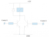
Now I would like both circuits to activate one relay. I would like to know if I can how to connect both circuits to a single relay. I came up with the following schematic, does this work? If not can anyone help me with a proper implementation?
Cheers,
Michiel
Currently I'm designing a protection board for my soon to build class A amplifier.
I would like to combine 2 circuits, one for startup delay of speakers and DC protection and the other is a temperature protection for the transistors.
Now I would like both circuits to activate one relay. I would like to know if I can how to connect both circuits to a single relay. I came up with the following schematic, does this work? If not can anyone help me with a proper implementation?
Cheers,
Michiel
Attachments
Thanks for the quick reply. Any recommendations for the circuits? There are so many different schematics available, I'm not sure which is best suited for my protection board.
I found a few circuits, are these ok for my needs?
First is Temperature Protection, second is Speaker Delay and DC Protection
Cheers,
Michiel
I found a few circuits, are these ok for my needs?
First is Temperature Protection, second is Speaker Delay and DC Protection
Cheers,
Michiel
Attachments

I wouldn't really know what to recommend without having tested them.
The DC offset looks a pretty standard arrangement. I'd like to know how it behaves in the event of a brief cycling of power. Does it work reliably ?
The temperature one looks OK-ish (you'll need the right type of thermistor). I say "ish" because I wonder what happens as T1 slowly comes into conduction and thus T2... slowly into conduction. I like to see an instant switchover which implies hysteresis (a bit like positive feedback).
If you want an idea for a speaker delay have a look at this. It could be adapted (as was discussed in a later post) to accept more "inputs" for other triggers.
http://www.diyaudio.com/forums/solid-state/224957-simple-universal-speaker-delay-using-triac.html
I once developed a dual function protection board prototype that had both dc protect as well as thermal protect.
However the thermal protect did not cut the speaker output, it had a dual stage comparator setup where the first stage turns on a cooling fan, and if thats not enough, power to the main transformer is cut until the amp cools down to near ambient with aid from the cooling fan.
I set the comparators to turn on the fan at around 50-60deg C and cut power at around 75-80deg C.
A BD139 wired as a diode was used for the sensor for thermal contact and ease of mounting, but a regular diode works just as well with no changes.
Just did some more searching and found a nice document on this site for delay and DC protection ")
http://www.diyaudio.com/media/build-guides/diyaudio-speakerprotector-build-guide-v1.0.pdf
http://www.diyaudio.com/media/build-guides/diyaudio-speakerprotector-build-guide-v1.0.pdf
Hi Michiel,
I'm using the TA7317 chip, which is specially designed for this job.
- input delay
- DC-protection
- fast turn of
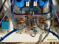
See the board below, if designed for a stereo amp.
Remark, the NC contact of the relays are connected to ground. This decreases the changes that the relay keeps stiking (welding effect) by a big DC on the output of the amps, see:
Speaker DC protection with relays
I'm using the TA7317 chip, which is specially designed for this job.
- input delay
- DC-protection
- fast turn of
See the board below, if designed for a stereo amp.
Remark, the NC contact of the relays are connected to ground. This decreases the changes that the relay keeps stiking (welding effect) by a big DC on the output of the amps, see:
Speaker DC protection with relays
Attachments
I'd like to point out that temp sense of case or heat sink is way too slow to protect output transistors. Mostly PA amp builders use microprocessors and current sense out now (current transformers), but for the last transistor-resistor-op amp math model for heat on the MJ15025 output transistor look at the schematic for the Peavey CS800X. The CS800s has the same current sensor but the logic is microprocessor from 1998.
You can cut the number of transistors etc by using the 8 v SPS Peavey uses, That breaks down at 8v if the speaker stays too long either way from return level. They filter it with a 47k resistor and a 2.2 uf bipolar cap, to cut trips on transients. You can buy a similar part at newark.com (farnell) the powerex BX08d. Peavey uses it to trip the crowbar SCR, but that melts PWB traces instead of tripping the power circuit breaker, so I am repurposing it to stop drive to a 4 pole relay to open the power rails.
You can cut the number of transistors etc by using the 8 v SPS Peavey uses, That breaks down at 8v if the speaker stays too long either way from return level. They filter it with a 47k resistor and a 2.2 uf bipolar cap, to cut trips on transients. You can buy a similar part at newark.com (farnell) the powerex BX08d. Peavey uses it to trip the crowbar SCR, but that melts PWB traces instead of tripping the power circuit breaker, so I am repurposing it to stop drive to a 4 pole relay to open the power rails.
'Not sure how and why you would sense excess temp. on a class A amplifier. Maximum dissipation is at minimum output. If it's just a general safety concern in case of say, regulated PSU failure, then a simple NC thermal switch close to the output stage on the 'sink will be more reliable than an electronic circuit.
However, I have seen a few large class A amps with thermal sensing and resettable cut-outs on the transformer. I think this is often more appropriate.
You can even cheaply buy toroids ready wound with these as they are used in low voltage lighting applications.
However, I have seen a few large class A amps with thermal sensing and resettable cut-outs on the transformer. I think this is often more appropriate.
You can even cheaply buy toroids ready wound with these as they are used in low voltage lighting applications.
- Status
- This old topic is closed. If you want to reopen this topic, contact a moderator using the "Report Post" button.
- Home
- Amplifiers
- Solid State
- Designing an amp protection board