Because i cant get help with this in tubes/valves section, i`m opening thread here with HOPE , that SOMEONE whould be able to HELP ME. 
I need help with the current/transistor section of the amp
Sorry -___- looks like dont know how to post smaller pics with the enlargement option.................
I`ve put just links for the second, and third picture
I`ve read thru part of the moskido thread, and few others, and there are some good ideas, and some not so good but i would like help for some of the designes, i havent seen in those threads I`ve made a few modifications to some projects, i have found., but i`m not experienced designer, nor so knowledgeable about suitable elements for the design, i want to achive/make So i want to present, design idea by design idea, and to finish it with your help
I`ll upload the original design(s) that inspired me, and the resulting one, to polish&finish it without blunders of type "ooooupss i didnt know that" with your help ^___^
I`m new to spice, so i`ll TRY to do something on my own, but dont hold your hopes to much for that XDDD
I will start with the design i saw/found in Elektor 1997 september
This is the tube section of the amp
this is the original current section
http://imageshack.us/a/img203/3061/hibrid1.jpg
and this is the modified current section
http://imageshack.us/a/img96/5227/enhancedhibridpr1s.jpg
For cheaper version up to +47/0/-47V i consider BD912 T6-T13 / BD911 T14-T21 with R20-R35=100ohms, and R36-R51=0,27ohm
For better option(and higher voltages), i consider 2SC2992/2SA1216 pairs and MJL15024/MJL15025 , MJL21193/MJL21194, 2SC5200/2SA1943 as other options
I need help with the current/transistor section of the amp
Sorry -___- looks like dont know how to post smaller pics with the enlargement option.................
I`ve put just links for the second, and third picture
I`ve read thru part of the moskido thread, and few others, and there are some good
ideas, and some not so good but i would like help for some of the designes, i havent seen in those threads I`ve made a few modifications to some projects, i have found., but i`m not experienced designer, nor so knowledgeable about suitable elements for the design, i want to achive/make So i want to present, design idea by design idea, and to finish it with your help I`ll upload the original design(s) that inspired me, and the resulting one, to polish&finish it without blunders of type "ooooupss i didnt know that"
with your help ^___^I`m new to spice, so i`ll TRY
to do something on my own, but dont hold your hopes to much for that XDDD I will start with the design i saw/found in Elektor 1997 september
This is the tube section of the amp
An externally hosted image should be here but it was not working when we last tested it.
this is the original current section
http://imageshack.us/a/img203/3061/hibrid1.jpg
and this is the modified current section
http://imageshack.us/a/img96/5227/enhancedhibridpr1s.jpg
For cheaper version up to +47/0/-47V i consider BD912 T6-T13 / BD911 T14-T21 with R20-R35=100ohms, and R36-R51=0,27ohm
For better option(and higher voltages), i consider 2SC2992/2SA1216 pairs and MJL15024/MJL15025 , MJL21193/MJL21194, 2SC5200/2SA1943 as other options
I started this thread because i didnt want to bury my posts under 200+ pages of posts in the moskido thread .......
Also i`m gona post some other moskido, and non moskido designs that i have modified, and in need of help for finishing them.
Can someone help me with sugestion about usable BJT-s, R20-R35 best values for the sugested BJT-s, and with boucherot-s network values, because i supose the old ones are not suitable for new design.
And how much smaller values can i use for resistors R18&R19???
Or should i open a new thread i solid state part of the forum???
@kenpeter: - CCS is not a junk, and has a good role i CMRR, and preventing the oscilation in mosfets.
Last edited:
yes,he should learn how to use "manage attachments" button...
wasn´t it possible to use two drain- and two sors- resistors at driver fets instead each bp output transistor having it´s own? simmilar output stage could been seen at boraomega´s (Borivoje Jagodić) "Lambda" and "CroSer" amplifiers. The description about those two amplifiers you can find at :::Borina Amaterska Svastara::: under AUDIO/POJAČALA/... boraomega said there that it was Andrej Lakner´s idea wich he used in those two amp´s,here are the schemes:
wasn´t it possible to use two drain- and two sors- resistors at driver fets instead each bp output transistor having it´s own? simmilar output stage could been seen at boraomega´s (Borivoje Jagodić) "Lambda" and "CroSer" amplifiers. The description about those two amplifiers you can find at :::Borina Amaterska Svastara::: under AUDIO/POJAČALA/... boraomega said there that it was Andrej Lakner´s idea wich he used in those two amp´s,here are the schemes:
Attachments
Last edited:
THANK YOUUU 44250 ! XD
Finaly, someone with something useful
I`ll try to learn manage atachements Those pics half of time pop-out in normal size, sometimes big, until then i`ll try for some pics to post just links for them
I`ve had a quick look at the pics of schematics you posted(realy realy nicely engineered amps, i`ll look in details later for shure) Yeah , i know its posible to put just one(like in compaund output stages) but if its like this i dont have to calculate the ohms, and the wattage is evenly distributed on every resistor, and any inductivity if i use cheaper resistors is lessen. Using both NPN and PNP on both upper, and down output stage parts should maximally cut down the crossover distortion+ the configuration allows puting double number of output transistors(in the drawing i`ve put 8(up)+8(down) because there was no place on paper for 4 more, for using BD911/BD912). In the MPA amp from elector(where they used BD-s, they used separate resistors for every transistor), and it has its advantages, also in that i wont have to hunt odd values of resistors for adding, or subtracting aditional transistors. But there is a catch, idealy all four transistors should be maximaly matched(quadruple matching), the minimum should be like in normal(matching upper, and downer device) npn/pnp matching(thanks to you 44250 i now have more transistors as an option for output devices )
Can you tell me something about R18/R19 in schematics, can i, and how smaller values can i put infront of mosfets ????
Finaly, someone with something useful
I`ll try to learn manage atachements
Those pics half of time pop-out in normal size, sometimes big, until then i`ll try for some pics to post just links for them I`ve had a quick look at the pics of schematics you posted(realy realy nicely engineered amps, i`ll look in details later for shure) Yeah , i know its posible to put just one(like in compaund output stages) but if its like this i dont have to calculate the ohms, and the wattage is evenly distributed on every resistor, and any inductivity if i use cheaper resistors is lessen. Using both NPN and PNP on both upper, and down output stage parts should maximally cut down the crossover distortion+ the configuration allows puting double number of output transistors(in the drawing i`ve put 8(up)+8(down) because there was no place on paper for 4 more, for using BD911/BD912). In the MPA amp from elector(where they used BD-s, they used separate resistors for every transistor), and it has its advantages, also in that i wont have to hunt odd values of resistors for adding, or subtracting aditional transistors. But there is a catch, idealy all four transistors should be maximaly matched(quadruple matching), the minimum should be like in normal(matching upper, and downer device) npn/pnp matching(thanks to you 44250 i now have more transistors as an option for output devices
)Can you tell me something about R18/R19 in schematics, can i, and how smaller values can i put infront of mosfets ????
The link in previous post is invalid now. Here is the new one, and new three more schemmatics
All schenatics in this post are UNFINISHED designes for which i need help with, from the people on this forum
These is the original starting point design for the schematics after this one.
hibrid project 2
http://imageshack.us/a/img560/1467/hibridpr21.jpg
hibrid project 3
http://imageshack.us/a/img407/1474/hibridpr3.jpg
hibrid project 4
http://imageshack.us/a/img90/3663/hibridpr4.jpg
hibrid project 5
http://imageshack.us/a/img266/1162/hibridpr5.jpg
All schenatics in this post are UNFINISHED designes for which i need help with, from the people on this forum
These is the original starting point design for the schematics after this one.
An externally hosted image should be here but it was not working when we last tested it.
An externally hosted image should be here but it was not working when we last tested it.
hibrid project 2
http://imageshack.us/a/img560/1467/hibridpr21.jpg
hibrid project 3
http://imageshack.us/a/img407/1474/hibridpr3.jpg
hibrid project 4
http://imageshack.us/a/img90/3663/hibridpr4.jpg
hibrid project 5
http://imageshack.us/a/img266/1162/hibridpr5.jpg
The link in previous post is invalid now. Here is the new one, and new three more schemmatics
All of the above haave fatal errors in the circuitry which will at least make it non-functional but in most cases instantly explode some transistors on power up. Which is what you get with simulator designs where someone has forgotten to simulate real world situations.
It says in the very first post (as you can see from the quote) that i`m not experienced circuit designer, or that knowledgeable, the other thing is that i started from the WORKING, and already proven circuits, NOT simulations. And know for a fact that modification of elektor hibrid DOESNT have errors(so it means your lying), but i think it could use a little optimisation/improvment.
I`ll upload the original design(s) that inspired me, and the resulting one, to polish&finish it without blunders of type "ooooupss i didnt know that"
I`m new to spice, so i`ll TRY
I will start with the design i saw/found in Elektor 1997 september
This is the tube section of the amp
An externally hosted image should be here but it was not working when we last tested it.
this is the original current section
http://imageshack.us/a/img203/3061/hibrid1.jpg
and this is the modified current section
http://imageshack.us/a/img96/5227/enhancedhibridpr1s.jpg
For cheaper version up to +47/0/-47V i consider BD912 T6-T13 / BD911 T14-T21 with R20-R35=100ohms, and R36-R51=0,27ohm
For better option(and higher voltages), i consider 2SC2992/2SA1216 pairs and MJL15024/MJL15025 , MJL21193/MJL21194, 2SC5200/2SA1943 as other options
Third thing is that i stated that other 4 projects are NOT FINISHED designes, and NEED adjusting/finishing.
So, from your post i can only conclude that you are very rude, and with bad intentions.
For those with good intention, and will/knowladge to help, i think maybe 2SK2221/2SJ352 pair could be used without any pains of adjusting/modificating the tube section. Any thoughts on that ?
Last edited:
And one corection,because of the desire, and speed to show the ideas wrong version of schematic is posted, the hibrid project 3 is reuploaded.
http://img191.imageshack.us/img191/328/hibridpr31.jpg
http://img191.imageshack.us/img191/328/hibridpr31.jpg
And one corection,because of the desire, and speed to show the ideas wrong version of schematic is posted, the hibrid project 3 is reuploaded.
http://img191.imageshack.us/img191/328/hibridpr31.jpg
And it still has the same error which will make at least the IRF9610 blow up on start-up and possibly the voltage regulators too.
I was not talking about the elektor schematic. That one will work OK although it would benefot from higher power supply voltage for the tube stage.
Starting from your post with the 8 schematics, every one has fatal errors as i said, because they are derived from your schematic number 2 in that post, which is a 'simulator design' by someone else, and it has the same design flaw, one which the simulator will not expose unless default conditions of simulation are changed and you know where to look.
Hint 1: positive rail regulation/filtering is in the wrong place.
Hint 2: search, this type of schematic has been analysed here before, several times.
Also if you accuse people of lying because you cannot understand how a circuit works and at the same time ask for help in getting the circuit to work, you will not get any help here.
I uploaded just project 3 because of the output stage. I did search specificaly for the hibrid schematics, here, and all over the net(for days, and days). The version with irf540/irf9540 pair is already proven, and built model, and the version with irf610/irf9610 pari is also built as far, as i could find. Both versions are A class amps, the first for 30-50w, the other is for headphones. The version for headphones, by my view can be used to drive output stage like in clasical SS amps diferential pair-VAS with CCS-output stage. But i have combined my favourite output configurations with this version, but i dont know, or better say dont have the experience to make the adjustments to make it whole(the values of resistors in the IRF-s drain to make it work in pure A class + to give enough current(not too much, not too little) for the output stage).
If i`m wrong, i`m sorry for the acusation of lying, but i searched(and diged HARD to find any info on hibrid amps,HERE and all over the net), so with that in mind, i whould like to show me where did you saw that info/discusion ^___^
Just not to be lazy, i plowed through the DIY again, and still at it, to find, data that tell a different story...... I whould apreciate help, with pointing me to the right direction
Just not to be lazy, i plowed through the DIY again, and still at it, to find, data that tell a different story...... I whould apreciate help, with pointing me to the right direction
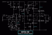
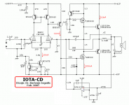
MINER, that what you want has been done long time ago...
IOTA-CD, OME - Pojacavaci snage - Power amps - DiyAudioProject
IOTA-CD, OME - Pojacavaci snage - Power amps - DiyAudioProject
Member
Joined 2009
Paid Member
You spelled it wrong. Search for "hybrid", not "hibrid"....i searched(and diged HARD to find any info on hibrid amps,HERE and all over the net)...
(If anyone still cares - I just noticed the threads a year old)
- Status
- This old topic is closed. If you want to reopen this topic, contact a moderator using the "Report Post" button.
- Home
- Amplifiers
- Solid State
- TUBE/MOSFET/BJT hibrid amp need help with mosfet/bjt section