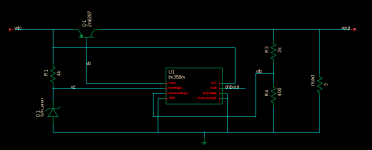
In simulation, what is the proper method to model a stability analysis of the following circuit?
Meaning where do I inject the AC signal and where do I look at the loop gain/phase? Do I need to inject the AC signal into vdc and look at vb? If so, what other modifications do I need to make to my testbench to properly model the analysis?
Meaning where do I inject the AC signal and where do I look at the loop gain/phase? Do I need to inject the AC signal into vdc and look at vb? If so, what other modifications do I need to make to my testbench to properly model the analysis?
Attachments
The most straightforward way (not 100% theoretically accurate, but more than sufficient) is to insert your AC source between FB and the NI input, and look at the ratio of VFB/VNI
What inaccuracies arise from this method?
The loading of the divider by the amplifier's input is not taken into accountWhat inaccuracies arise from this method?
Here it is; the circuit had to be adjusted to display something usable as the original values were too crazy, but the principle remains the same whatever the exact circuit.Elvee, do you mind posting a simulation schematic of your test circuit for stability analysis?
Attachments
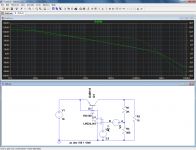
YesV3 is the AC source correct?
Displaying a nice downwards sloping curve as expected, instead of an ugly flat one (not connected with simulation issues).And what purpose does the 1n4148 serve?
-30 degrees phase margin at the 0 dB gain intercept means its an oscillator, not a regulator
base pullup R is always used in real circuits
the pass Q adds gain depending on load current to the loop so compensation is required somewhere - heavier overcompensation is required for larger load range, C on the reg output has a big impact on stability
base pullup R is always used in real circuits
the pass Q adds gain depending on load current to the loop so compensation is required somewhere - heavier overcompensation is required for larger load range, C on the reg output has a big impact on stability
Here it is; the circuit had to be adjusted to display something usable as the original values were too crazy, but the principle remains the same whatever the exact circuit.
Hmm, Elvee for some reason the circuit that you posted does not work for stability analysis. I had to put a large series L and large C to the AC source to get the analysis to work.
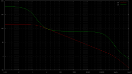
With that said, I'm finding this setup stable without any compensation. Why is this? I modeled my opamps to have a similar open loop frequency response as in the datasheet of the LM358. Is this because the low gain bandwidth product of the opamp?
Attachments
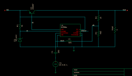
Probably some restriction of the simulator you use.Hmm, Elvee for some reason the circuit that you posted does not work for stability analysis. I had to put a large series L and large C to the AC source to get the analysis to work.
Could be many reasons, transistor not conforming to model, parasitic inductance in the input loop, etcWith that said, I'm finding this setup stable without any compensation. Why is this?
- Status
- This old topic is closed. If you want to reopen this topic, contact a moderator using the "Report Post" button.
- Home
- Amplifiers
- Solid State
- How to model stability analysis of a linear regulator such as this?