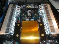
nice sound, no on off thumbs,
Attachments

")
well ... isn't that another insane powerholic circuit ?
There is no Vi limiter in the design .... you cannot design amplifiers of this power without it ( especially if its supposed to be used in pro use ) which of course input limiter is also required
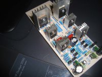
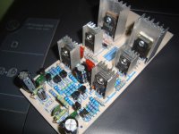
The semis you are using on the prototype are low quality which also increase operating risk
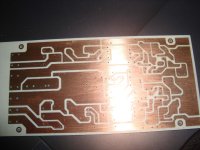
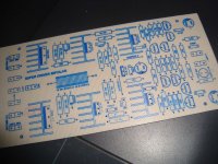
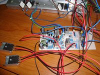
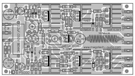
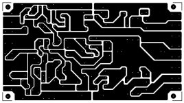
Even though the pcb looks pretty neat the actual amplifier could run in to many wiring problems ta could be caused from high current frequency complication and so on..
It might work in simulation but not in real life....
150pf miller caps ? i wonder about the sonic signature of this amplifier ..
Sorry ...i don't like it
There is no Vi limiter in the design .... you cannot design amplifiers of this power without it ( especially if its supposed to be used in pro use ) which of course input limiter is also required
The semis you are using on the prototype are low quality which also increase operating risk
Even though the pcb looks pretty neat the actual amplifier could run in to many wiring problems ta could be caused from high current frequency complication and so on..
It might work in simulation but not in real life....
150pf miller caps ? i wonder about the sonic signature of this amplifier ..
Sorry ...i don't like it
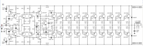
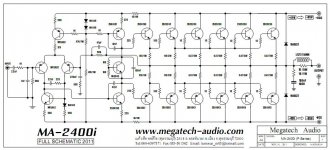
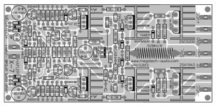
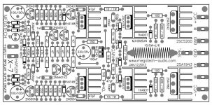
The driver transistors, 2SA1962 and its compliment have to dissipate 23 Watts at full power, (Hfe of output transistors, average 35) and will need a decent heat-sink. I do not like the 47R resistors in the emitters of the Norton Mirrors, it reduces the reactance of each respective mirror and can become unstable.
I think there is no need for a current drive limiter circuit as this output stage can take out most loads and it should light up an single bar electric fire element with ease!
The driver transistors chosen in this design, in class D, will produce 3kW (15Amp at 200Volts) without the output stage transistors. A simple triangular waveform generator feeding the inverting input and audio supplied to the non inverting input of an Op Amp will suffice to produce a pulse width modulated square wave drive. A few more decoupling capacitors will need to be employed to stop power supply noise.
Clive Sinclair made the class popular for Hi Fi systems back in 1960. He used a pair of OC71 germanium transistors. They are rated at a maximum current of 180mA and produced 10Watts of audio into a 7.5Ohm loud speaker!
Why not use FETs. They are cheaper and require far less drive current and no source resistors are required and they just match the drive voltage to the output impedance.
When I work out how to add png files, I will post a novel FET power amplifier design that works very well.
next project,
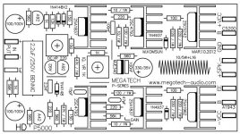
here is the schematic.
Attachments
- Status
- This old topic is closed. If you want to reopen this topic, contact a moderator using the "Report Post" button.
- Home
- Amplifiers
- Solid State
- 100w to 1000w class ab