I did a recap of my TA-5650 V-Fet some time back. Replaced diodes too. I did not pay particular attention to the type of electrolytic cap I put in, assuming that new was better.
Time has passed, knowledge gained (I hope), and now I think I may revisit and change some standard caps with low ESR ones. Yep, should have known this then...
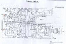
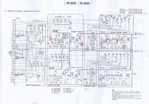
Not planning to redo all, but only the coupling caps in the signal path. In attached schematics I think I have identified the essential ones (orange).
I understand that the Panasonic FR-types may be a suitable choice. Available here: EEUFR1H100 - PANASONIC - CAPACITOR, RADIAL, 50V, 10UF | Farnell Nederland
So two questions: 1) did I pick the proper candidates and 2) did I pick a proper make?
Thanks, Jan
Time has passed, knowledge gained (I hope), and now I think I may revisit and change some standard caps with low ESR ones. Yep, should have known this then...
Not planning to redo all, but only the coupling caps in the signal path. In attached schematics I think I have identified the essential ones (orange).
I understand that the Panasonic FR-types may be a suitable choice. Available here: EEUFR1H100 - PANASONIC - CAPACITOR, RADIAL, 50V, 10UF | Farnell Nederland
So two questions: 1) did I pick the proper candidates and 2) did I pick a proper make?
Thanks, Jan
Attachments
With those values (0u47-10u) you've highlighted, I suggest using film capacitors instead for AC coupling. Film capacitors have practically zero DC leakage and much lower dissipation factor compared to aluminum electrolytic capacitors. Digikey carries the Kemet R82 series and Panasonic ECQ-V stacked metal films that are compact in size and reasonably priced. I don't know what is available in your area but you get the idea. Most aluminum electrolytic capacitors even low leakage types are poor choice for AC coupling anyway, they have significantly higher DC leakage (compared even to tantalums) that in time will make volume controls permanently scratchy.
The Panasonic FR series are specifically designed for switching power supplies where DC leakage is not an issue and ESR at 100kHz should be low as possible. You can use the FR series for DC filtering, supply decoupling and AC bypass.
The Panasonic FR series are specifically designed for switching power supplies where DC leakage is not an issue and ESR at 100kHz should be low as possible. You can use the FR series for DC filtering, supply decoupling and AC bypass.
Just looking at the circuit and I think you've missed a few out that are important audio-wise ")
C103 and C212, both large electrolytics and both hugely important. C305 in the power amp is also just as important as any coupling cap.
Also C308/9, although not in the audio path could if they are degraded or gone high E.S.R. allow for premature and unpredicatable operation of the protection circuits.
Thanks!
Film caps: Digikey (Kemet) doesn't go higher than 4u7. Farnell goes further, but any film cap I could find would be way too big to fit, sizes are like 22x30x12 mm etc.
So assuming at least some should be electrolytic, and if not the Panasonic FR, then what would be a suitable candidate?
Also thanks for pointing out those other caps. I can follow why these are of importance too.
Thanks!
So assuming at least some should be electrolytic, and if not the Panasonic FR, then what would be a suitable candidate?
I know Nelson Pass (Pass Labs) is a great fan of Elna Silmic caps. They might be worth a try. Available from Digikey.
RFS-50V100MG3#5 Elna America | 604-1119-ND | DigiKey
For the 10uF, use 2 4u7 in parallel , mount one on the solder side of the board if you are running out of space on the component side. Don't worry about the reduction in capacitance, electrolytics have a much looser tolerance of +/-20% or higher for some types.
The FR series are OK for AC bypassing where DC leakage is not an issue just like the component designators that Mooly pointed out. Bypass them with 100nF film capacitors to improve their high frequency characteristic.
The FR series are OK for AC bypassing where DC leakage is not an issue just like the component designators that Mooly pointed out. Bypass them with 100nF film capacitors to improve their high frequency characteristic.
Thanks!
Film caps: Digikey (Kemet) doesn't go higher than 4u7. Farnell goes further, but any film cap I could find would be way too big to fit, sizes are like 22x30x12 mm etc.
.
Last edited:
Sony changed the design...
Now here is where it gets interesting:
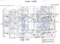
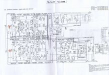
1) For serial nrs. over 501,900 Sony changed the values of C103 (from 2200 uF/10V to 470 uF/35V) and C305 (from 220 uF/6.3V to 100 uF/35V). C212 remained the same.
Now, why would they change the capacity? The surrounding resistors and operating voltages remained unchanged.
Where I am worried that my caps may not be the best type, imagine the effect of changing the capacity by a factor of 4 and 2...
2) Also Sony upped the voltage of most coupling caps (C101/C205/C213/C230/C315) from 25V or 50V all to 100V.
Why would they change the voltages? Again the test-voltages shown are identical with the previous design.
Changed schematics attached.
My serial is 506,585 so it would apply to mine, which means that I may have ordered wrong caps...
Could use some expert advice here!
Just looking at the circuit and I think you've missed a few out that are important audio-wise
C103 and C212, both large electrolytics and both hugely important. C305 in the power amp is also just as important as any coupling cap.
Now here is where it gets interesting:
1) For serial nrs. over 501,900 Sony changed the values of C103 (from 2200 uF/10V to 470 uF/35V) and C305 (from 220 uF/6.3V to 100 uF/35V). C212 remained the same.
Now, why would they change the capacity? The surrounding resistors and operating voltages remained unchanged.
Where I am worried that my caps may not be the best type, imagine the effect of changing the capacity by a factor of 4 and 2...
2) Also Sony upped the voltage of most coupling caps (C101/C205/C213/C230/C315) from 25V or 50V all to 100V.
Why would they change the voltages? Again the test-voltages shown are identical with the previous design.
Changed schematics attached.
My serial is 506,585 so it would apply to mine, which means that I may have ordered wrong caps...
Could use some expert advice here!
Attachments
1) C103 is an interesting one.. it could have just been a printing error on the schematic ? It is part of the phono input, so if you dont use that, you dont have to worry too much. My guess is the reduction to 470uF was so that part of the circuit (looks like a bootstrap) would stabilise quicker.
C305 was likely just because there was no loss of performance with it being 100uF, and they use 100uF @ 35v elsewhere. Larger will not hurt at this particular part of the circuit.
2) Well there is not 100V at those nodes, so dont panic. It was probably just to do with some manufacturing supply issue.
Both those caps have to have a value "large enough" such that they don't roll off the frequency response at the bottom end. Make them too large and the amp takes much longer to stabilise at power on.
"Where I am worried that my caps may not be the best type, imagine the effect of changing the capacity by a factor of 4 and 2
It doesn't quite work like that The value and "quality" of the cap are two different things. If the different value caps changed the roll off point from (say) 1 Hz to 4 Hz you wouldn't be able to tell any difference whatsoever. But change the quality of the caps and you would.
"Where I am worried that my caps may not be the best type, imagine the effect of changing the capacity by a factor of 4 and 2
It doesn't quite work like that
The value and "quality" of the cap are two different things. If the different value caps changed the roll off point from (say) 1 Hz to 4 Hz you wouldn't be able to tell any difference whatsoever. But change the quality of the caps and you would.1) C103 is an interesting one.. it could have just been a printing error on the schematic ? It is part of the phono input, so if you dont use that, you dont have to worry too much. My guess is the reduction to 470uF was so that part of the circuit (looks like a bootstrap) would stabilise quicker.
C305 was likely just because there was no loss of performance with it being 100uF, and they use 100uF @ 35v elsewhere. Larger will not hurt at this particular part of the circuit.
C103: I think it was deliberate and not an error. The values are also shown on the PCB layouts. I do use the (V-fet powered) phono quite a lot actually. Speed could be a reason.
C305, assuming this was deliberate too, what would Sony want to achieve?
My electronics knowledge is limited, but I think this works as a low pass filter? So a reduction in capacity increases the frequency range at the low end to pass through to the amp?
2) Well there is not 100V at those nodes, so dont panic. It was probably just to do with some manufacturing supply issue.
Could it be that they did get fried on the earlier amps? I do agree that the voltages shown do not make it logical at first sight. Further down C101 there is 97V on the power supply, but that doesn't get to the caps.
C103: I think it was deliberate and not an error. The values are also shown on the PCB layouts. I do use the (V-fet powered) phono quite a lot actually. Speed could be a reason.
C305, assuming this was deliberate too, what would Sony want to achieve?
My electronics knowledge is limited, but I think this works as a low pass filter? So a reduction in capacity increases the frequency range at the low end to pass through to the amp?
Could it be that they did get fried on the earlier amps? I do agree that the voltages shown do not make it logical at first sight. Further down C101 there is 97V on the power supply, but that doesn't get to the caps.
The increase to 100V is probably simply that they had suitable 100V capacitors on the production line already, so they decided to use them. I really wouldn't worry about it.
You are right about C305, it is a filter so that the amplifier does not amplify any DC offset. It is common in a lot of power amp designs. It should be large enough that the low end frequency response is not excessively limited, but small enough that the turn-on thump is not excessive. The thump is mitigated by the output relay however.
- Status
- This old topic is closed. If you want to reopen this topic, contact a moderator using the "Report Post" button.
- Home
- Amplifiers
- Solid State
- Sony TA-5650 - coupling caps