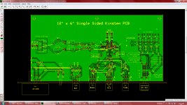
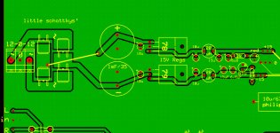
A few have asked where I have been hiding! Just idling along at the moment but still very interested in the electronics hobby. This is a pcb for a cloned preamp using TL084 chip. Not finished completely but close; any ideas on that drps ripple filter would be appreciated - we have 240VAC/50Hz in Tasmania.
Cheers, Jack
Cheers, Jack
Attachments
Hi Jack!
Apologies for the late reply. I've looked at the circuit this is based on (from your email: http://www.escol.com.my/kits/ES-027.html) and a few things about it are a little bit old-school and maybe not as good as it otherwise could be.
For instance the gain of the preamp is 13.5 you really only need a gain of 2, this will give you greater control over the volume. Also, you really don't need a loudness control and from my own experience tone controls negatively impact on the sound to the point that I no longer use them. However should you feel that you'd like to use tone controls, check out Rod Elliott's preamp with tone control circuit: http://sound.westhost.com/project97.htm
Personally I'd recommend an inverting buffer followed by a 10k pot, then a non-inverting stage with a gain of 2 then another inverting buffer to bring it back to absolute phase (I'll post a schematic of what I mean when I get home from work). This is very easy (and cheap) to construct and will give you the best performance for what you need. Although you could just get away with having the inputs coming directly into a 10k pot followed by a non inverting stage with a gain of 2.
Although, if you've already built it and it sounds good then that's all that matters. Hifi is always about personal preference, especially when it's DIY.
Last edited:
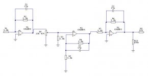
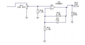
The first pic is a completely buffered preamp and the second is a simple 2x gain non-inverting preamp based after a 10k pot.
All opamps should be bypassed with 100nF polyesters and 10uF electrolytics. If you're not sure if your power amp has an input cap, add a 4.7uF bipolar of your choice to the output.
I hope you're having fun with your DIY
All opamps should be bypassed with 100nF polyesters and 10uF electrolytics. If you're not sure if your power amp has an input cap, add a 4.7uF bipolar of your choice to the output.
I hope you're having fun with your DIY
Attachments
- Status
- This old topic is closed. If you want to reopen this topic, contact a moderator using the "Report Post" button.