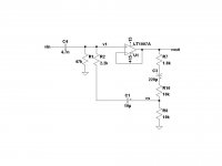
in this circuit i considered the gain of the op.amp to be equal to 1, so v1=vout, then i calculated vs using the voltage divider rule which gives:
vs= v1*(R8/(R8+((R2*(R7+R10))/(R2+R7+R10))))
then i wrote a node equation in v1
(vin-v1)sC4-v1/R1-(v1-vs)/R2=0
considering v1=vout i substituted for vs in the second equation which gives:
vout/vin=-C4 s/(-C4 s+(-1+R8/(R2 (R7+R10)/(R2+R7+R10)+R8))/R2-1/R1)
then i calculated the magnitude which gives:
|vout/vin|=C4 w/(sqrt ((-C4 w)^2+((-1+R8/(R2 (R7+R10)/(R2+R7+R10)+R8))/R2-1/R1)^2))
ltspice gives a -3dB point at 3.140kHz.
where is my mistake?
Attachments
1)
Not the same by a factor of 1000 .
2) your comparison is meaningless.
You are comparing a formula/equation for which you do not provide a numerical value, to a number.
3) *FULLY* agree with Mooly's assessment, of course.
Only adding that since we are studying a high pass filter, its effect will be seen at some low or mid cutoff frequency.
That said, you are showing a poorly designed active high pass filter.
R2 presents an "active" value larger than the normal one, because it is bootstrapped
As an example of the two extremes, if it were straight grounded, it would show its regular value: 2K2.
If it were connected to U1's out, it would show "infinite" value.
If it were connected to a point receiving 1/2 V out, it would show double its value.
In that case, without need to simulations, a simple mental calculation tells me that this high pass filter has a corner frequency around 6500Hz .
*But* in a proper designed active filter, R2 value should be much higher than that of R7/8/10 ... which is not the case.
Try again but with R2, say, 22K ; R8/10 1K and R7 180 ohms and results will be more in line with what is expected.
And really R7 in series with R10 is unnecessary, drop one and if necessary adjust the value of the other.
IMPORTANT: are you using the European convention ( "." means one thousand) or the USA one ("." is a decimal point )?3.140kHz
Not the same by a factor of 1000 .
2) your comparison is meaningless.
You are comparing a formula/equation for which you do not provide a numerical value, to a number.
3) *FULLY* agree with Mooly's assessment, of course.
Only adding that since we are studying a high pass filter, its effect will be seen at some low or mid cutoff frequency.
That said, you are showing a poorly designed active high pass filter.
R2 presents an "active" value larger than the normal one, because it is bootstrapped
As an example of the two extremes, if it were straight grounded, it would show its regular value: 2K2.
If it were connected to U1's out, it would show "infinite" value.
If it were connected to a point receiving 1/2 V out, it would show double its value.
In that case, without need to simulations, a simple mental calculation tells me that this high pass filter has a corner frequency around 6500Hz .
*But* in a proper designed active filter, R2 value should be much higher than that of R7/8/10 ... which is not the case.
Try again but with R2, say, 22K ; R8/10 1K and R7 180 ohms and results will be more in line with what is expected.
And really R7 in series with R10 is unnecessary, drop one and if necessary adjust the value of the other.
in this circuit i considered the gain of the op.amp to be equal to 1, so v1=vout, then i calculated vs using the voltage divider rule which gives:
vs= v1*(R8/(R8+((R2*(R7+R10))/(R2+R7+R10))))
then i wrote a node equation in v1
(vin-v1)sC4-v1/R1-(v1-vs)/R2=0
considering v1=vout i substituted for vs in the second equation which gives:
vout/vin=-C4 s/(-C4 s+(-1+R8/(R2 (R7+R10)/(R2+R7+R10)+R8))/R2-1/R1)
then i calculated the magnitude which gives:
|vout/vin|=C4 w/(sqrt ((-C4 w)^2+((-1+R8/(R2 (R7+R10)/(R2+R7+R10)+R8))/R2-1/R1)^2))
ltspice gives a -3dB point at 3.140kHz.
where is my mistake?
Everything is fine up to the nodal equation and the decision to substitute v1=vout. From there onwards I can't understand the equations anymore due to the huge numbers of parentheses.
Anyway, I find a time constant of 50.87787832 us, corner frequency of 3128.175709 Hz when I start with the equations I can still read and write out everything else myself. That is not far from 3140 Hz. Like you, I've assumed that the electrolytic caps are short circuits, maybe that explains the remaining 12 Hz somehow.
Have you done any dimensional checks? If you are for example adding a dimensionless number to an admittance somewhere, you know there is a mistake.
I also wonder why the circuit is so complicated. For example, R2 could be disposed of altogether when you tweak the resistors in the voltage divider a bit to make its output resistance 2200 ohm higher.
Last edited:
Short answer: make the pot value 1/10 of R2, or the "parasitic" pot resistance you are adding throws calculations out of whack.
Slightly longer:
the concept behind this design is varying the impedance of R2 by applying a fraction of the output voltage on its "ground" end.
As I mentioned above, if this end is connected to ground, its impedance is its resistive "passive" value: 2K2 .
If you connect it to V out, its value is infinite.
At intermediate values, the impedance will take an intermediate value too Vs.
*BUT*, if you get Vs from a potentiometer, you are introducing new, unwanted, "passive" resistance in the net.
So best would be to add a buffer between the pot slider and R2 or, as a compromise solution, use a low value pot.
1/10 the R2 value would be acceptable.
Yet you chose a 22K pot, 10X R2's value !!! A poor choice.
And, among other things, it throws the transfer curve out of whack.
So, redo your design with more sensible values.
Or forget the "active" part, replace R1 with a 47K pot, follow it with a unity gain buffer, and call it a day.
Why do you assume that the potmeter's output resistance is unwanted? OK, it makes the mathematics somewhat more complicated, but davidel94's calculations already include this effect. To me it makes more sense to choose a potmeter value that provides a pleasant control, and I have no idea if that would mean a small or a large potmeter resistance.
Exactly, that's the point.To me it makes more sense to choose a potmeter value that provides a pleasant control,
And the pot value chosen does not provide it.

Well, I doand I have no idea if that would mean a small or a large potmeter resistance.
The idea behind modifying a resistor value by bootstrapping (it's what we are doing here) lies in applying to "the other end" a controlled fraction of the audio voltage applied to it.
Notice the word: "voltage".
The ideal voltage source has zero internal impedance.
This would be achieved by buffering the wiper voltage as I suggested earlier.
Very easy and cheap to achieve, just adding an inexpensive unity gain Op Amp.
You gain 2 advantages here by doing it the right way:
a) the pot response is *smooth*
b) the Math becomes simpler, more straightforward, because you do not need to add and compensate for, the disrupting influence of that too high value pot
Read this article:
BOOTSTRAPPING
See how the bootstrapped input resistor (R2 in Davide's example) appears as a *much* higher value , in this case they apply as much bootstrap *voltage* as they can; in the active filter the amount is variable.
See how simple Math becomes, when properly designed.
See also that in the equivalent circuit analysis, voltage sources are used.
Now, if you do not want to add an extra buffer (which really is as simple as specifying a dual Op Amp, instead of that single one), you may reach a very acceptable compromise by specifying a pot value quite lower than R2 resistance.
Or rising appreciably the value of R2.
One can simplify the equations a bit by defining:
Rd=R7+R8+R10
R7+R10=alpha*Rd
Hence, R8=(1-alpha)*Rd. In the original design, the minimum value of alpha is 0.08256... due to the 1.8 kohm fixed resistor.
Assuming that the voltage follower is ideal and that the electrolytic capacitors are short circuits, the cut-off radian frequency becomes:
omega_n=1/(R1*C4)+(1/(R2*C4))*(alpha/(1+(Rd/R2)*alpha*(1-alpha)))
With a voltage follower or with a negligible value of Rd, this simplifies to
omega_n=1/(R1*C4)+alpha*(1/(R2*C4))
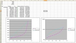
That is, using a linear potmeter, with extra voltage follower or very low potmeter resistance you get a constant number of Hz per degree of rotation of the control knob. That's nice if that is what you want, but I could imagine that for an audio application it is more convenient to have a constant number of degrees per octave instead. In fact neither the original circuit nor the counterproposal provide a constant number of degrees per octave, but the original does come closer up to 6000 Hz or so. See the attached figure, with logaritmic Y-axis the tuning plot for the original looks somewhat more straight up to 6 kHz. Maybe some intermediate potmeter resistance would better match an exponential law than either of the two alternatives.
In the end, I don't really know what the circuit is for or what the requirements are. I know it must be something audio-related because this is the DIYaudio forum, but that's about it. Not knowing what the intentions of the designer were, I for one can't judge whether he has done his job well.
Rd=R7+R8+R10
R7+R10=alpha*Rd
Hence, R8=(1-alpha)*Rd. In the original design, the minimum value of alpha is 0.08256... due to the 1.8 kohm fixed resistor.
Assuming that the voltage follower is ideal and that the electrolytic capacitors are short circuits, the cut-off radian frequency becomes:
omega_n=1/(R1*C4)+(1/(R2*C4))*(alpha/(1+(Rd/R2)*alpha*(1-alpha)))
With a voltage follower or with a negligible value of Rd, this simplifies to
omega_n=1/(R1*C4)+alpha*(1/(R2*C4))
That is, using a linear potmeter, with extra voltage follower or very low potmeter resistance you get a constant number of Hz per degree of rotation of the control knob. That's nice if that is what you want, but I could imagine that for an audio application it is more convenient to have a constant number of degrees per octave instead. In fact neither the original circuit nor the counterproposal provide a constant number of degrees per octave, but the original does come closer up to 6000 Hz or so. See the attached figure, with logaritmic Y-axis the tuning plot for the original looks somewhat more straight up to 6 kHz. Maybe some intermediate potmeter resistance would better match an exponential law than either of the two alternatives.
In the end, I don't really know what the circuit is for or what the requirements are. I know it must be something audio-related because this is the DIYaudio forum, but that's about it. Not knowing what the intentions of the designer were, I for one can't judge whether he has done his job well.
Attachments
Last edited:
Hi Davide,
After browsing through your design report of your entire audio system, I have the following comments:
1. I'm impressed! I am an electronics engineer who has been building electronics as a hobby since the age of nine, but I wasn't doing anything nearly this advanced when I was eightteen years old. Do you intend to become an electronics professional? You obviously have talent.
2. I find your section about noise somewhat incomplete. For example, bipolar transistors also have base shot noise and base current 1/f noise. You make a general statement about shot noise being negligible, but without explaining under which conditions this is true and whether you mean base or collector shot noise.
3. The distortion plot figure 6 is not showing any distortion, just an FFT calculation noise floor or the FFT of an initial transient. Presumably you need to cut off a larger part of the beginning of the waveform, tighten simulation tolerances and/or reduce the maximum time step further until you actually see the harmonics. Figure 7 looks much better. The graphs in your power amplifier chapter all look fine.
By the way, are your op-amp models supposed to model distortion accurately? Some macromodels are quite primitive.
4. Stability
It is actually possible for an amplifier to have a 360 degree phase shift around the loop at a frequency where the magnitude of the loop gain is greater than 1 and still be stable. This is called conditional stability (in the control-theoretical sense of the word, in RF electronics it means something else). It is used a lot nowadays in sigma-delta analogue to digital and digital to analogue converters and in class D amplifiers. Conditionally stable circuits have the reputation of bursting into oscillation when they clip, but there are ways to avoid that. Besides, circuits that are supposed to be unconditionally stable sometimes do burst into oscillations at clipping. Stability under small signal conditions really doesn't guarantee anything about what will happen during recovery from clipping.
Best regards,
Marcel van de Gevel
- Status
- This old topic is closed. If you want to reopen this topic, contact a moderator using the "Report Post" button.
- Home
- Amplifiers
- Solid State
- calculate the transfer function