")
Thanks.BB,
Very nice circuit, carefully designed and built. It would sound marvellous, I'm sure. A choke is the best way to almost efficiency. You should be to reach 46Vpp output?
Cheers,
Hugh
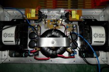
I`ve used the transformer I had so is 32Vpp with 2A bias in 8 Ohms load.
Bogdan, interesting schematics, with GNFB of a current type. I guess it has voltage gain around factor 7...8. Some things are not attractive to me, too much points with electrolytic caps, especially C5 in the NFB chain. Could you measure the value of output impedance?
I was also thinking that if the voltage of the output node wasnt too far above ground that the capacitors in the feedback could be eliminated with only a change in X1 (bias pot) value to give higher adjustment range.
Bogdan, interesting schematics, with GNFB of a current type. I guess it has voltage gain around factor 7...8. Some things are not attractive to me, too much points with electrolytic caps, especially C5 in the NFB chain. Could you measure the value of output impedance?
Yes the voltage gain is 8x. C5 is film cap and it`s not in NFB chain. If you meant C6, I tried without it and the amp is thermaly unstable (bias depends on the Q6 themperature).
I don`t have the measuring equipment , but simulation says 0.0096 Ohms.
Last edited:
I also thinking that if the voltage of the output node wasnt too far above ground that the capacitors in the feedback could be eliminated with only a change in X1 (bias pot) value to give higher adjustment range.
The resistance of the coil is 0.9 ohms and that gives 1.8 Volts on the output with 2A bias, so in this case output cap is a must.
Yes the voltage gain is 8x. C5 is film cap and it`s not in NFB chain. If you meant C6, I tried without it and the amp is thermaly unstable (bias depends on the Q6 themperature).
I don`t have the measuring equipment , but simulation says 0.0096 Ohms.
Output impedance modulus can be measured without difficulties.
Just measure sine 1kHz RMS output voltage without load (V1), then connect resistive load R Ohms (around 4...8 Ohms) and measure output voltage (V2). These three values say all about impedance modulus at 1kHz.
If you do not have sine signal generator, just some CD with various test signals could be used.
Also it would allow us to check how much the sims can be trusted.
Last edited:
Having in mind the amount of GNFB used I think that simulation can be trusted in this case.... simulation says 0.0096 Ohms.
I've mentioned Zout just from curiosity. Actually, this parameter does not tell me too much about how double bass string is reproduced.
My long term subjective observation is, the lower intrinsic Zout of output stage alone, without action of GNFB, the more natural and vivid will be sound of double bass strings.
For example, 70mOhms Zout of NoGNFB amp are much better than 7mOhms or 100mOhms Zout of amps, where Zout is almost completely "emulated" by GNFB action.
Speaker-amp interaction is rather compex process, but the trend mentioned above has quite a solid ground to me.
The compensation network values ruin the PSRR.
C1 need not to be higher than 47pF , while R39 should be better 1K
or even suppressed along with C26.
Other than this , the THD is quite low , wich is not surprising given
the high GNFB ratio , while the output Z has a minimum of about 4mR
at mid frequency and rise linearly on the low frequency side given the
capacitive coupling and the same on the high frequency side due
to inductive coupling.
Attachments
The compensation network values ruin the PSRR.
C1 need not to be higher than 47pF , while R39 should be better 1K
or even suppressed along with C26.
Tried that, the amp oscilates in real life, with C1 47pF.
- Status
- This old topic is closed. If you want to reopen this topic, contact a moderator using the "Report Post" button.
- Home
- Amplifiers
- Solid State
- TheTwelve SE class A TMC amplifier