A friend recommended this circuit. was tested and simulated (proteus 7) but does not work in the simulation. help me to modify to get more probecho sizes. has a good sound.
excuse my bad English
un amigo me recomendo este circuito. fue probado y simulado (proteus 7) pero en la simulacion no funciona. me ayudan a modificar de talles para sacarle mas probecho. tiene un buen sonido.
excuse my bad English
un amigo me recomendo este circuito. fue probado y simulado (proteus 7) pero en la simulacion no funciona. me ayudan a modificar de talles para sacarle mas probecho. tiene un buen sonido.
Attachments
I think you should add some emitter resistors to Q1,Q2,Q3 and Q4
Q3 and Q4 might not be needed at all If you reduce the value of the feedback resistor and connect it directly to midpoint of emitter resistor of Q1 and Q2.
You should also consider to reduce gain in VAS stage, unless you like the sound of amps with huge amount of negative global feedback.
Cheers
Q3 and Q4 might not be needed at all If you reduce the value of the feedback resistor and connect it directly to midpoint of emitter resistor of Q1 and Q2.
You should also consider to reduce gain in VAS stage, unless you like the sound of amps with huge amount of negative global feedback.
Cheers
Something is not right in input. I believe q1 and q3 should be npn and their emitters should be connected to R5 and not q2 and q4. Q4 and q2 emitters should be connected to r4, and r4 and r5 should not be connected. Looks similar to leach amp input stage, or other similar symmetrical designs. Emitter resitors on the input stage improves linearity, but should work with or without.
")
If the bases and emitters are tied together, the transistor won't be biased on. Emitters on q1 and q3 have to be -.6 volts below base, and q2 and q4 have to be +.6 volts. And if you are going to eliminate one pair of inputs, then have to convert voltage gain stage on that side to current source or boot strap circuit.
Agree and add.
For that and other errors , I suggest you start by building a classic, well known amp, while you continue studying at your own pace.
The simulation did not lie to you, it showed it does not work.
Sorry.
Nota: pasa tu texto por un corrector gramatical *antes* de traducir.
El traductor no sabe qué quisiste decir porque busca en su diccionario interno.
Por ejemplo, no tradujo "probecho" porque no la encontró, y es lógico, se escribe "provecho".
Suerte.
Thanks friends ...
The feedback resistor of the high is because these amplifiers are commonly used by people who like more noise. Today you install this amp in stereo, which had damaged the amplifier, with good results.
A point in favor of this amplifier is temperature in low output transistors.
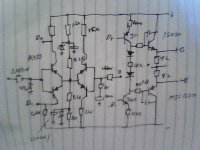
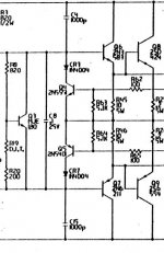
This pattern was interpreted photocopying a plane that is used in the workshop. The transistors shown in proteus are not actually used the originals.
TN2905A = A733
TIP42 = MJE15031
TIP41 = MJE15030
TIP3055 = 2SC5200
TIP2955 = 2SA1943
This I did for the lack of proteus library.
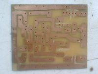
Tomorrow montare photos PBC (misinterpretation??), Where I extracted the schema and photos mounted amplifier.
Gracias por el consejo JMFahey lo que pasa es que escribí un poco apresurado por el trabajo…
The feedback resistor of the high is because these amplifiers are commonly used by people who like more noise. Today you install this amp in stereo, which had damaged the amplifier, with good results.
A point in favor of this amplifier is temperature in low output transistors.
This pattern was interpreted photocopying a plane that is used in the workshop. The transistors shown in proteus are not actually used the originals.
TN2905A = A733
TIP42 = MJE15031
TIP41 = MJE15030
TIP3055 = 2SC5200
TIP2955 = 2SA1943
This I did for the lack of proteus library.
Tomorrow montare photos PBC (misinterpretation??), Where I extracted the schema and photos mounted amplifier.
Gracias por el consejo JMFahey lo que pasa es que escribí un poco apresurado por el trabajo…
Hello everyone thanks for contribution ....
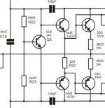
Diagram corrected (amp.pdf)
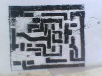
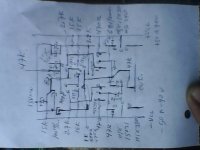
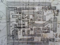
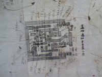
Perform a misunderstanding and I apologize for that. The images (IMG0469A, IMG0470A,) shows the schematic used as a reference for building and PCB.
SREGOR:'re right Q1 and Q3 are NPN. The schematic is not very clear (IMG0470A) ... I'll take into account your notes ...
Propose improvements that would be a multiplier Vbias (eg Vbias1, vbias2 apex) with limitations.
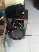
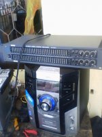
Note: This amplifier circuit is working on a Mini Hi-Fi Music System (IMG0471A, IMG0472A), with excellent results.
Diagram corrected (amp.pdf)
Perform a misunderstanding and I apologize for that. The images (IMG0469A, IMG0470A,) shows the schematic used as a reference for building and PCB.
SREGOR:'re right Q1 and Q3 are NPN. The schematic is not very clear (IMG0470A) ... I'll take into account your notes ...
Propose improvements that would be a multiplier Vbias (eg Vbias1, vbias2 apex) with limitations.
Note: This amplifier circuit is working on a Mini Hi-Fi Music System (IMG0471A, IMG0472A), with excellent results.
Attachments
You are trying to build a GAS Grandson with a simpler bias circuit and no DC servo.
Download the GAS Grandson of Ampzilla schematic for free - Hifi Manuals
You will need to register and use a browser other than Firefox.
Download the GAS Grandson of Ampzilla schematic for free - Hifi Manuals
You will need to register and use a browser other than Firefox.
Hello everyone thanks for contribution ....
Diagram corrected (amp.pdf)
Perform a misunderstanding and I apologize for that. The images (IMG0469A, IMG0470A,) shows the schematic used as a reference for building and PCB.
SREGOR:'re right Q1 and Q3 are NPN. The schematic is not very clear (IMG0470A) ... I'll take into account your notes ...
Propose improvements that would be a multiplier Vbias (eg Vbias1, vbias2 apex) with limitations.
Note: This amplifier circuit is working on a Mini Hi-Fi Music System (IMG0471A, IMG0472A), with excellent results.
This schematics will NOT work.
The transistors will need to be biased before You should continue this.
Just look at the crossover distorsion you have in your graphs there.
Last edited:
- Status
- This old topic is closed. If you want to reopen this topic, contact a moderator using the "Report Post" button.
- Home
- Amplifiers
- Solid State
- your input on this amplifier circui(su opinión respecto a este circuito amplificador)