I am measuring 2vdc at the speaker and cannot find out where it is coming from. I am not to good with solid state gear but usually can figure out these sort of things but this has been a real bugger for me.
Any advice is well appreciated and thanks in advance.
Any advice is well appreciated and thanks in advance.
Attachments
Did you check the voltages as shown on the diagram?
Do they track?
Edit: there is no imherent balancing mechanism in this amp - it all depends on how well the various parts match and track with temperature, so I would definitely not expect super low offset. Whether 2V is reasonable, hard to say.
Is this amp really used for a speaker load?
Is there an (invisible) coupling cap downstream?
jan
Last edited:
Not a lot of suspects here.
I wouldn't be surprised if You find the guilty one among the four transistors.
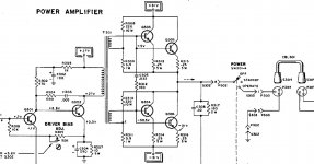
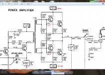
Check the voltage between R308 - R309, and between R310 - R311 and see if they indeed are what the schema says, eg: +0,5V and -30,5V.
If those are OK, there isn't much other than either the Q303, Q304, Q305 or the Q306.
Try to disconnect one pair at the time, (Desconnect the R313 and R314 first) end meassure the voltage at the output. If OK, then resolder those two and try again with the R315 and R316 disconnected.
If now the voltage is OK, then you simply exchange the TWO transistors of wich you have disconnected the emitterresistors on. The new pair should be a matched pair.
I wouldn't be surprised if You find the guilty one among the four transistors.
Check the voltage between R308 - R309, and between R310 - R311 and see if they indeed are what the schema says, eg: +0,5V and -30,5V.
If those are OK, there isn't much other than either the Q303, Q304, Q305 or the Q306.
Try to disconnect one pair at the time, (Desconnect the R313 and R314 first) end meassure the voltage at the output. If OK, then resolder those two and try again with the R315 and R316 disconnected.
If now the voltage is OK, then you simply exchange the TWO transistors of wich you have disconnected the emitterresistors on. The new pair should be a matched pair.
increase the value of R311, i.e. try 4.7ohm 1W.
This will let both lower transistors conduct more, hence the output voltage will drop.
If this is not precise enough, try 8.2 ohms 1W for R311 and parallel this with a 47 ohm pot and adjust to zero. Measure the value of these combined resistors and replace for a fixed one.
Dick
This will let both lower transistors conduct more, hence the output voltage will drop.
If this is not precise enough, try 8.2 ohms 1W for R311 and parallel this with a 47 ohm pot and adjust to zero. Measure the value of these combined resistors and replace for a fixed one.
Dick
Check the value of R309.
It's not likely that the 10 watt resistors have changed value as they are probably wirewound. The 1 watt resistors are probably carbon.
It's also possible that one of the transistors is showing some C-B leakage which is causing the base voltage to rise.
It's not likely that the 10 watt resistors have changed value as they are probably wirewound. The 1 watt resistors are probably carbon.
It's also possible that one of the transistors is showing some C-B leakage which is causing the base voltage to rise.
Resistor 309 is carbon comp and measured 4.5R
Resistor 311 is also carbon comp and measured 5.3R
Both 10w 220R resistors were close to spec, R308 being 219 and R310 measured 221.5. Both 220R resistors are not wirewound, they are made by Milwaukee and look to be ceramic.
Like I stated before I am more of a hollow state guy and never got into the SS so excuse my ignorance. I guess my assumption was that transistors usually don't leak but fail and that would short the collector voltage internally causing a fuse to blow.
Did you check the voltages as shown on the diagram?
Do they track?
Edit: there is no imherent balancing mechanism in this amp - it all depends on how well the various parts match and track with temperature, so I would definitely not expect super low offset. Whether 2V is reasonable, hard to say.
Is this amp really used for a speaker load?
Is there an (invisible) coupling cap downstream?
jan
Yes the amp is hooked directly up to speakers without any coupling cap between power amp and speaker output.
Transistors have several failure modes. A C-E short is the most often seen. A transistor which has operated at a high temperature can show other signs of impending failure. B-C or B-E leakage is not at all unusual. Please make sure that the mounting screws are tight.
All transistors are fastened to the large heatsinks tightly.
Thanks for the info
") . So I guess I will try some different resistors and if that doesn't do the trick than I will have to replace the transistors.
. So I guess I will try some different resistors and if that doesn't do the trick than I will have to replace the transistors.UPDATE!!!!!!!!!!!!!!!!!!!!!!!!!!!!!!!!!!!!
I just installed a 3w 1ohm resistor in series with resistor 309 making it 6ohm total. I am now at 300mv dc at speaker, MUCH BETTER!. So resistor 311 is 5.3 and total resistance for 309 is 6ohm, is this because the transistors are not matched that they need different value gain resistors?
I just installed a 3w 1ohm resistor in series with resistor 309 making it 6ohm total. I am now at 300mv dc at speaker, MUCH BETTER!. So resistor 311 is 5.3 and total resistance for 309 is 6ohm, is this because the transistors are not matched that they need different value gain resistors?
Last edited:
I suspect theese transistors either is very warm, or defect.
The values of the 1W-resistors seemed very high. A 3,9 Ohm resistor should not reach 4,5 Ohms. And with 6 Ohms on R309 the voltage would increase quite a bit ther, over 1,5 Volts or something like that now, is it?
It should be reduced to 3,9 Ohms to get the voltage down, and the same for R311
The values of the 1W-resistors seemed very high. A 3,9 Ohm resistor should not reach 4,5 Ohms. And with 6 Ohms on R309 the voltage would increase quite a bit ther, over 1,5 Volts or something like that now, is it?
It should be reduced to 3,9 Ohms to get the voltage down, and the same for R311
I do not suspect the transistor for now.
There is no DC balancing circuit there; the centerpoint/speaker_out is centered brute force by the string of resistors R308/309/310/311 , just like that.
To be more precise:
1) both rails must be symmetrical respective to ground.
2) you must have the same voltage drop across R308 and R310
3) you must have the same voltage drop across R309 and R311.
If not,replace them with proper value.
Your matching the higher value is dangerous, you will overbias and overheat them; stick to design values.
4) anyway, I'm quite sure that your 2V offset will disappear or drastically reduce when you connect a speaker as a load.
Without load yes, you may have somewhat higher offset, but that causes no problems.
EDIT: which of the big VOX amps is it?
Do you have the original cabinet?
Last edited:
- Status
- This old topic is closed. If you want to reopen this topic, contact a moderator using the "Report Post" button.
- Home
- Amplifiers
- Solid State
- DC voltage at speaker output