Hi all,
Please, I need some advice on this amplifier, because after ten years of SET, I needed an amp capable of driving speakers at 2 ohms, after trying it, it is his job without problem, as the sound is pretty good, I wanted to restore it, as some components are not original.
This is where I need your skills, whether it's worth changing the Predriver, are the transistors Q3, Q4, Q5, Q6 on the diagram.
On my amp they are MPSA05, MPSA55K, they seem to be matched (small paint strokes).
I wanted to put the sa818y, sc1628y, they are expensive, but I can get them,
bandwidth is not the same, is that it can change the sound?, is that it is a mistake to try to change them?
Transistors for power on the left channel, there are ARC4700C, 4800B, for the right, MJ15024, mj15025.
There are some small differences sound between the two, is it better to put the same motorola, or the ST2121, ST5949?
I also have a question for Mr.llwhtt, please, is it I could get the procedure to adjust this amp?
Thank you,
Best Regards.
Stefano
Attachments
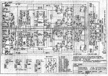
The transistors you mention are the input differentials, the pre-drivers are Q11,12,13, and 14. I will look for my Andromeda service manual tonight, but I believe it's 14mv across the emitter resistors, R65-R72.
Can you get a schematic for an FM Acoustics FM300A amplifier? It's made in Switzerland and there is absolutely no info here in the US. I have a butchered one here and could use a schematic. Thanx.
Craig
Can you get a schematic for an FM Acoustics FM300A amplifier? It's made in Switzerland and there is absolutely no info here in the US. I have a butchered one here and could use a schematic. Thanx.
Craig
I found my Andromeda I service manual and the bias adjustment is as follows:
1. With power off, face the PCB from foil side and remove fuse on left, closest to the edge of PCB.
2. Connect DC ammeter across fuse clips. Turn power on and observe meter for 60ma + or - 5ma while heat sink is cold. Current will drift up as heat sink temp. rises. No load, no signal.
3. Adjust R73 if not in spec.
4. Turn power off, replace fuse.
5. Repeat for right side of PCB, remove fuse, connect ammeter, turn power on and check for 60ma, adjust R74 for 60ma if needed.
6. repeat for other channel.
Hello,
thank you for your reply,
I was writing my text, when you had already answered, I put it as is:
Unfortunately, I do not know anyone with this type of amp, their website does not say much, apparently, FM, wants to maintain a certain mystery, only few elected through a strict selection can afford the object desire, or something in this genre there.
The only time I saw a semblance schema, as well as several photographs of printed circuits and components
it was the site of a repairman Japanese
by the translation of the text, it has Interogation points on some transistor, probably custom built without reference.
It was one of the first FM I can not remember the model, there was a cooling tunnel horizontally arranged inside the chassis.
For the Sumo, I want to explain some symptoms,
when I turn it on, it makes a little plop in speakers,
then by vibrating against the transformer, it is a cyclical noise increases, and then it almost disappears, but I hear a grinding noise in the speakers, is that the diode bridge is tired, or capacitors, or improper adjustment.
Channel with Motorola, heat a little more than the channel with the ARC.
Anyway, I'll change all capacitors including ceramic.
For the imput differential, Q3-Q4-Q5-Q6 (thank you for correcting my mistake),I would like to change by the original or replacement, according to Japanese datasheet (sa1145-sc2705), if there is an effect on the sound, otherwise if you're telling me that MPSA05 and 55 are very good, because it does no difference in this case I do not exchange.
There are also Q15-Q17, Q16-Q18, 3 are 2sb595y (hfe120-240), and 1 2sb595o (hfe70-140), the complementary transistors 2sd525y were replaced by TIP31C.
You surely understand, I'm not electronics, but I think that all these components, which are not original (unless there have been several versions of this amplifier) can affect the overall balance of the amplifier.
I have several multimeters, but no oscilloscope,
Is an adjustment can be made into 2 ohms with multimeter?
Best Regards
Stefano
Using a current meter is much easier than trying to get to the emitter resistors on that amp, I sold my two Andromedas almost 20 years ago so I forgot about the mechanics of that amp. If you have two DMMs you can set the bias on both sides of one channel at the same time.
Craig
Craig
Stefano,
Thank you for posting the schematic for this amp. I have always liked the Sumo amps and it is to bad that the company went away. I wouldn't mind building one of these amplifiers myself. Don't know that I can but perhaps with the right help here on this site I could do it.
Steven
Thank you for posting the schematic for this amp. I have always liked the Sumo amps and it is to bad that the company went away. I wouldn't mind building one of these amplifiers myself. Don't know that I can but perhaps with the right help here on this site I could do it.
Steven
Hello,
I just finished adjusting the two modules, as described by Mr.craig.
For the left channel, there was an imbalance of 22mA, ie: 91 and113mA,
for the right channel, it was not better, it also warmed more, as I described earlier: 34mA, 93 and127mA, the bias was set rather hot
I adjusted at about 62.5mA.
DC is +-46.5volt.
Then I wanted to see how it sounds, I would say that before the sound was pulsed
a little faster and a little more control at the bottom.
I have this amp for about three weeks,
it would take a long time, it was set like this, because the previous owner did not know that the power transistors were changed.
Provided it is well balanced, I could keep the bias a little hotter, or it creates a problem of cross between transistors?
Best Regards
Stefano
Stefano,
Thank you for posting the schematic for this amp. I have always liked the Sumo amps and it is to bad that the company went away. I wouldn't mind building one of these amplifiers myself. Don't know that I can but perhaps with the right help here on this site I could do it.
Steven
Fortunately, the schematic is on the internet.
I do not know much about the topologies of the amp, I read that this amp to be placed on the market, was considered excellent,
at an affordable price, this is perhaps why it is not so much copied.
Stefano
Stephano,
When I was showing my speakers at the CES show in Las Vegas one year Sumo loaned me amplifiers to use during the show. I liked the sound very much and thought that later I would purchase one of their amps. But alas what happened was that Sumo shut down production. I remember reading something in their history about this but don't remember exactly why it happened. I think the designer passed away at some point if I am correct. So though these were nice sounding amps they haven't been available for a long time. I have some Parasound amplifiers that just never had the full bodied sound of the Sumo. Actually I have an older Harmon Kardon amplifier that sounds better than the Parasounds. Now to find out if anyone has ever cloned one of these amplifiers? I'll have to put up a post and ask that question.
Steven
Stephano,
When I was showing my speakers at the CES show in Las Vegas one year Sumo loaned me amplifiers to use during the show. I liked the sound very much and thought that later I would purchase one of their amps. But alas what happened was that Sumo shut down production. I remember reading something in their history about this but don't remember exactly why it happened. I think the designer passed away at some point if I am correct. So though these were nice sounding amps they haven't been available for a long time. I have some Parasound amplifiers that just never had the full bodied sound of the Sumo. Actually I have an older Harmon Kardon amplifier that sounds better than the Parasounds. Now to find out if anyone has ever cloned one of these amplifiers? I'll have to put up a post and ask that question.
Steven
Hello Mr.Steven,
Well, me too if I am not mistaken, Mr. James Buongiorno is indeed still alive.
Look at this link:James Bongiorno Designs
Best Regards
Stefano
Steven: Jason Stoddard from sumo is now running a primarily headphone audio company (Schitt Audio, yes you read that right....) making home amps and dacs. i'm not aware of who was the amp designer at Sumo, but Jason was certainly A designer at sumo and designs the amps at Schitt, likes circlotrons and uses a Sumo Andromeda III to drive some large planar panels at home. it might be worth shooting him an email through his website.
wit looks only a mother could love, that blue and gold chassis at James Buongiorno is UGLY
so in short, Steven, if you can remember exactly what amp it was, good chance you'll be able to find the schematic and maybe even PCBs here. there have been recent Ampzilla group buys, ive seen numbers of sumo 9 builds over the years
so in short, Steven, if you can remember exactly what amp it was, good chance you'll be able to find the schematic and maybe even PCBs here. there have been recent Ampzilla group buys, ive seen numbers of sumo 9 builds over the years
Last edited:
In regards to contacting Jason about SUMO, I contacted him last year and he has NO interest in dredging up the past. He answered some Andromeda II questions for me but wasn't interested in doing anymore.
Mike Moffet from the original Theta is there also but has no interest in the past either.
Craig
Mike Moffet from the original Theta is there also but has no interest in the past either.
Craig
Happy New Year to all,
I would like to complete this thread, but I have some problems to find certain components.
I would like to know if anyone knows the difference (if there is difference) between MPQ6001 and, SPQ1561 I found the datasheet of the IC MPQ6001, but not the SPQ1561.
My amp is installed SPQ1561,One is partially dead,for me, they are hard to find,
is that they are interchangeable?,
because surplussales Nebraska, has in stock MPQ6001, and in this case, I can change the four IC.
Thank you,
Best Regards
Stefano
Both should work equally well as both are listed on the schematic and in the service manual. Another alternative is to replace the IC with discrete transistors. If you can find MPSA13 & 63 darlingtons you will only need two transistors per channel. Did you try searching for MPQ6001 on this forum, there are several prior postings concerning this IC and alternatives. Whatever you end up doing make sure the IC/transistors are in contact with the heatsink, use thermal compound too.
Craig
Craig
Hello,
after a few months, I take this discussion, I had to wait a long time, the time to find all the components at the last moment, a channel came and went, it was the diodes and 2sa968 who had died, even if measured well (the amp was mounted with 968-2238-y and y, instead of 968B-y-y and 2238b).
I also found the sa818, sc1628, with great difficulty, but after listening, I preferred the sa1145 and sc2705, they go very well with a 60mA bias and are much more transparent, the 818 and 1628 asked a bias very high, if the distortion was audible.
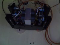
It remains for me that changing the power transformer is very noisy.
Apart from a few original resistors else is new (this amp is not a deal but it is very good).
I had a question about the secondary voltages, as for 42volt, I measured 47volt and 48volt for I measured 55volt.
Does it may be appropriate, or it is better to have tensions closest as that recorded in the diagram.
stefano
after a few months, I take this discussion, I had to wait a long time, the time to find all the components at the last moment, a channel came and went, it was the diodes and 2sa968 who had died, even if measured well (the amp was mounted with 968-2238-y and y, instead of 968B-y-y and 2238b).
I also found the sa818, sc1628, with great difficulty, but after listening, I preferred the sa1145 and sc2705, they go very well with a 60mA bias and are much more transparent, the 818 and 1628 asked a bias very high, if the distortion was audible.
It remains for me that changing the power transformer is very noisy.
Apart from a few original resistors else is new (this amp is not a deal but it is very good).
I had a question about the secondary voltages, as for 42volt, I measured 47volt and 48volt for I measured 55volt.
Does it may be appropriate, or it is better to have tensions closest as that recorded in the diagram.
stefano
Attachments
Hello,
after a few months, I take this discussion, I had to wait a long time, the time to find all the components at the last moment, a channel came and went, it was the diodes and 2sa968 who had died, even if measured well (the amp was mounted with 968-2238-y and y, instead of 968B-y-y and 2238b).
I also found the sa818, sc1628, with great difficulty, but after listening, I preferred the sa1145 and sc2705, they go very well with a 60mA bias and are much more transparent, the 818 and 1628 asked a bias very high, if the distortion was audible.
It remains for me that changing the power transformer is very noisy.
Apart from a few original resistors else is new (this amp is not a deal but it is very good).
I had a question about the secondary voltages, as for 42volt, I measured 47volt and 48volt for I measured 55volt.
Does it may be appropriate, or it is better to have tensions closest as that recorded in the diagram.
stefano
Can you get a schematic for an FM Acoustics FM300A amplifier? It's made in Switzerland and there is absolutely no info here in the US. I have a butchered one here and could use a schematic. Thanx.
Craig
Do you still have this amplifier? Where you able to repair it?
- Home
- Amplifiers
- Solid State
- Sumo Andromeda predriver advice