I'm trying to find the phase angle of the transfer function of a 2nd order high-pass filter. the phase should vary from 180° at w=0 to 0 at w = infinite
the transfer function with s substituted by jw is:
-w^2/((2*j*w/(C*R2))-w^2+(1/(C^2*R2*R1)))
I set the cut-off frequency at 20 Hz.
the numerator has no complex part so it doesn't introduce a phase shift while in the denominator the phase shift is -arctan(Im/Re) which is the arctan of the ratio of the immaginary part on the real part.
so the phase angle becomes:
-arctan((2*w*C*R1)/(1-(w^2*C^2*R2*R1)))
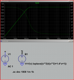
but if you see the excell file I attached the phase from 0 to 18 Hz goes from 0° to -90° and then it goes from 90° to 0°. I think that the problem is that the function arctan is defined between -90° and + 90° so it cannot give higher or lower angles. to solve this problem I summed 180° to the angle of the frequencies lower than 20 Hz and left unchanged the other angles so the plot becomes right. but is this the way to work with phase angles? is my method right?
the transfer function with s substituted by jw is:
-w^2/((2*j*w/(C*R2))-w^2+(1/(C^2*R2*R1)))
I set the cut-off frequency at 20 Hz.
the numerator has no complex part so it doesn't introduce a phase shift while in the denominator the phase shift is -arctan(Im/Re) which is the arctan of the ratio of the immaginary part on the real part.
so the phase angle becomes:
-arctan((2*w*C*R1)/(1-(w^2*C^2*R2*R1)))
but if you see the excell file I attached the phase from 0 to 18 Hz goes from 0° to -90° and then it goes from 90° to 0°. I think that the problem is that the function arctan is defined between -90° and + 90° so it cannot give higher or lower angles. to solve this problem I summed 180° to the angle of the frequencies lower than 20 Hz and left unchanged the other angles so the plot becomes right. but is this the way to work with phase angles? is my method right?
it helps to use tools specific for the application domain - they often have correct assumptions built in
in this case you need to look up "phase wrapping"/"unwrapping" - find a math package that does it right for you - or know when you have to correct by hand http://www.google.com/#hl=en&sugexp...8b13d38ba68b9&bpcl=39967673&biw=1920&bih=1069
even LTspice sometimes makes strange phase plots because it has to assume a starting phase for a circuit - the phase may be asymptotic beyond the frequency range you give it for the analysis - so knowing what to expect, interperting the plot, identifying likely software errors is still required
Attachments
Last edited:
A two pole high pass filter transfer function has two zeros in the numerator and two poles in the denomonator. As the frequency becomes large, the poles and zeros cancel and the transfer function magnitude becomes unity at infinite frequency. The two zeros are coincident at zero in the complex plane, so you start off with 180 degrees of phase shift from the two zeros. Since the poles are conjugate, their phase contribution cancels at zero frequency because the phases are equal and opposite. As the frequency increases, the phase from the poles starts to subtract from the 180 degrees of phase contributed by the zeros, and as the frequency approaches infinity, the phase approaches 0 degrees. You have 180 degrees of phase from the zeros and -180 degrees of phase from the poles.
so is the phase formula or the transfer function wrong?
There are two ways in order to calculate the arctg function. From -90° to +90° and from -180° to +180°. Look in Wikipedia to the functions atan and atan2.
If you want to get more angle for the phase rotation of the transfer function, you will have to produce your own code in order to have this wanted value of phase rotation. It is not difficult to produce if you think at what occurs with complex numbers in the circle and in which quadrant you are with this phase.
Kind regards
Rephil
- Status
- This old topic is closed. If you want to reopen this topic, contact a moderator using the "Report Post" button.
- Home
- Amplifiers
- Solid State
- phase angle of a transfer function