I guess I need to round up a mouser order.
Cool.
Srinath.
Why do you think the transformer was shot? What did you do to it? Last time I came to this thread (moons ago) I thought you had the standby LED working and IC451 put out a 5.6V DC as supposed. Have you lost the LED and the 5.6V now?
If you do have the 5.6V then the transformer is most likely good. What voltage do you have at R455 where it joins C466? You should have greater than 12V DC there. If you do have 12V or more there, do a quick test, pull fuse F452 (so that you don't power up the whole amp by doing the test), wire a 470 ohm or 1K ohm resistor from the 5.6V (at IC451 output) to the emmitor of Q456, you should engage all three relays (451, 452, and 453) by doing this. If the test turns out positive, measure the voltage at pin89 of IC701 (the Sony CXP micro) on the front board.
Last edited:
Not done
I have not done this test even though you ahve suggested it earlier.
I will get the board back to original and try it. I hope I didn't toss that old trafo.
Cool.
Srinath.
If you do have the 5.6V then the transformer is most likely good. What voltage do you have at R455 where it joins C466? You should have greater than 12V DC there. If you do have 12V or more there, do a quick test, pull fuse F452 (so that you don't power up the whole amp by doing the test), wire a 470 ohm or 1K ohm resistor from the 5.6V (at IC451 output) to the emmitor of Q456, you should engage all three relays (451, 452, and 453) by doing this. If the test turns out positive, measure the voltage at pin89 of IC701 (the Sony CXP micro) on the front board.
I have not done this test even though you ahve suggested it earlier.
I will get the board back to original and try it. I hope I didn't toss that old trafo.
Cool.
Srinath.
I didn't realize you have taken the original transformer off the board....then with it off the board a simple resistance measurement to the windings should tell you it's likely good or bad, you can in turn decide to or not to put it back on the board for the test I proposed. The test was all about ruling out the failure of the standby power supply and failure of the relay drive circuit. You can do that test with your substitute transformer (from the tape deck), if its output voltage is within the ball park. It would not make any sense to put back a transformer that does not even pass a resistance test.
If you decide to get a new transformer, an alternative to mouser transformer would be to find a suitable voltage/capacity rating wall wart adapter in your parts bin and gut the transformer out.
If you decide to get a new transformer, an alternative to mouser transformer would be to find a suitable voltage/capacity rating wall wart adapter in your parts bin and gut the transformer out.
Last edited:
I read through this whole thread -
This is what I observed in jan.
The transformer I pulled out made 13.4 volts ac. Its primary side tested like a capacitor. The one I put in made 10.4v ac. It tested like a resistor.
And the relays didn't click in either case.
If the original trafo is bad, I still ahve another issue ... maybe the one that killed that trafo - but its primary was bad - and the trafo I have in it, isn't enough voltage to do the trick.
Cool.
Srinath.
18v dc
An 18 or so DC one would do the job right ?
OK let me look, I've been using those guys to power a slew of LED lights. Has to be an 18 v somewhere.
Cool.
Srinath.
I didn't realize you have taken the original transformer off the board....then with it off the board a simple resistance measurement to the windings should tell you it's likely good or bad, you can in turn decide to or not to put it back on the board for the test I proposed. The test was all about ruling out the failure of the standby power supply and failure of the relay drive circuit. You can do that test with your substitute transformer (from the tape deck), if its output voltage is within the ball park. It would not make any sense to put back a transformer that does not even pass a resistance test.
If you decide to get a new transformer, an alternative to mouser transformer would be to find a suitable voltage/capacity rating wall wart adapter in your parts bin and gut the transformer out.
An 18 or so DC one would do the job right ?
OK let me look, I've been using those guys to power a slew of LED lights. Has to be an 18 v somewhere.
Cool.
Srinath.
I read through this whole thread -
This is what I observed in jan.
The transformer I pulled out made 13.4 volts ac. Its primary side tested like a capacitor. The one I put in made 10.4v ac. It tested like a resistor.
And the relays didn't click in either case.
If the original trafo is bad, I still ahve another issue ... maybe the one that killed that trafo - but its primary was bad - and the trafo I have in it, isn't enough voltage to do the trick.
Cool.
Srinath.
13.4VAC sounds a bit high.
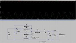
I did a simulation with 11.3VAC and it puts out a DC voltage just above 13V at 135mA load current, which seems to be comfortable for the relays and their protection resistors. The red trace shows the DC voltage after the diode bridge, the green trace shows the wave form at the 5.1V zener D458. I'll post another simulation with a 18VDC and see how much difference there would be.
Attachments
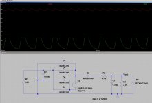
With a transformer that puts out 18VDC @180mA load current, there isn't much change to the waveform at D458. But the relays may not be spec-ed to operate at such a voltage even with the 33-ohm protection resistors in place, and you may want to be careful. I'm not saying it will not work though.
Attachments
I read through this whole thread -
This is what I observed in jan.
The transformer I pulled out made 13.4 volts ac. Its primary side tested like a capacitor. The one I put in made 10.4v ac. It tested like a resistor.
And the relays didn't click in either case.
If the original trafo is bad, I still ahve another issue ... maybe the one that killed that trafo - but its primary was bad - and the trafo I have in it, isn't enough voltage to do the trick.
Cool.
Srinath.
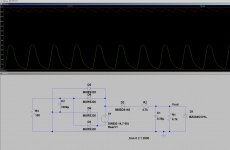
I too suspect the problem isn't with the power board. Even with a 10.4VAC trans the DC voltage output is still above 12V, more than enough to operate the relays with the 33-ohm resistors in place. See simulation below. But you may still want to first rule out the power supply and the relay drive circuits prior to troubleshooting elsewhere. So do the test I proposed. You can do it with the 10.4V trans.
I also noticed from reviewing the previous posts that you probably never mentioned the standby LED, when you turn the power on/off with the tack switch or a remote, the LED should change color. Did you ever see that happened?
Attachments
The LED did not change color after the first few steps.
I got this receiver with a working 2 channel amp.
I traced the problem to a blown out something in the dsp board I think, and when I reassembled it, it would not come out of standby.
I'll read this and the other threads I started on this amp to help remember.
Cool.
Srinath.
I got this receiver with a working 2 channel amp.
I traced the problem to a blown out something in the dsp board I think, and when I reassembled it, it would not come out of standby.
I'll read this and the other threads I started on this amp to help remember.
Cool.
Srinath.
Yea I fixed 2 swollen caps in the dts board and it refused to get out of standby after that.
When the dts was being fixed it powered up fine without the board, and with it it worked in 2 channel very well.
After I fixed the dts board and put it in, it refused to get out of standy.
Then removing the dts board did nothing to change that, its still not comming out of standby.
Cool.
Srinath.
When the dts was being fixed it powered up fine without the board, and with it it worked in 2 channel very well.
After I fixed the dts board and put it in, it refused to get out of standy.
Then removing the dts board did nothing to change that, its still not comming out of standby.
Cool.
Srinath.
I am pretty sure the original transformer is around 24v. Why I think so ...
I measured output from pin 1 of the trafo to the ground, I had 13.4v ac. The other 1/2 had to be 13.4 as well, so its a 27v ac trafo under 0 load.
My tape deck one is 10.4 - I think its not going to do.
However I also have to do the test by applying voltage to the transistor like suggested by nattwa and tauro on 2 different occassions 6 months apart - so that means I have to find the blooming original trafo, or get a replacement of that size and spec.
I have a onkyo 806 I gutted, I could find what it has ...
Cool.
Srinath.
I am pretty sure the original transformer is around 24v. Why I think so ...
I measured output from pin 1 of the trafo to the ground, I had 13.4v ac. The other 1/2 had to be 13.4 as well, so its a 27v ac trafo under 0 load.
My tape deck one is 10.4 - I think its not going to do.
However I also have to do the test by applying voltage to the transistor like suggested by nattwa and tauro on 2 different occassions 6 months apart - so that means I have to find the blooming original trafo, or get a replacement of that size and spec.
I have a onkyo 806 I gutted, I could find what it has ...
Cool.
Srinath.
I think you measured the transformer output the wrong way. The secondary winding is followed by a bridge rectifier and a smoothing cap therefore it does not have a pure AC reference to the ground. When you thought you were measuring the AC of the secondary winding by probing it in reference to the ground, there is in fact a large DC offset to it (equivalent to 1/2 of the DC voltage at the rectifier output), therefore, the reading can be inaccurate if your meter responds to such DC offset. The correct way would be probing across the two terminals of the winding directly.
However if your multimeter AC range does not respond to a DC offset the reading of 13.4V is indeed the output of that winding.
Since the two terminals are of the same secondary winding you cannot add the readings.
Just go ahead and do the test with the 10.4V transformer, also observe the standby LED.
Last edited:
In that circuit diagram - I see the diode rectifier bridge - D454, 5, 6, 7. But where is the smoothing caps.
I had to measure it to ground for some reason - I dont recall why, maybe the access was hard.
My DMM - its a cheapo $10 rat shack one. It is digital though.
Cool.
Srinath.
I had to measure it to ground for some reason - I dont recall why, maybe the access was hard.
My DMM - its a cheapo $10 rat shack one. It is digital though.
Cool.
Srinath.
Hi,
You can connect 120 volt AC to the primary and a 300 ohms connected to the secondary and read the voltage. One of the test I think I told you to do was to remove the fuse and check the current. You should read from possible 20 ma to 300 ma. The fuse size it is 500 ma. Now if you read resistance in the primary and secondary the transformer it is possible it is good. But still it may fail under load.
You can connect 120 volt AC to the primary and a 300 ohms connected to the secondary and read the voltage. One of the test I think I told you to do was to remove the fuse and check the current. You should read from possible 20 ma to 300 ma. The fuse size it is 500 ma. Now if you read resistance in the primary and secondary the transformer it is possible it is good. But still it may fail under load.
- Status
- This old topic is closed. If you want to reopen this topic, contact a moderator using the "Report Post" button.
- Home
- Amplifiers
- Solid State
- What does +3v3a mean in a schematic