A couple of days ago I got a mail from a guy who asked if I could make a PCB for a active Magneplanar 1.6 filter shown at:
http://home.comcast.net/~dreite/Magnepan16/Magnepan16.htm
I finished the PCB layout yesterday, and did some additional AC simulations just for the fun of it, but I was surprised of the result.
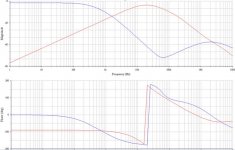
The output became the plot shown below.
Form my point of view and my experience so far I think this filterresponse looks pretty terrible.
There’s almost no flat area for the highpass part, and the -3dB frequencies for the low- and highpassfilters are “placed” far away from each others so there becomes a severe dip in the frequency response.
I have no experience with Magneplanar 1.6, but the guy who have made those filters claims that they represent the same transfer function as the original filters found in the speakers.
So what’s so special with those speakers if they need filters with the kind of frequencyresponse shown below?
And will the active filter be a good replacement for the original filter?
I’m still wondering about the frequency response for this filter, I can’t really understand why the speakers or anyone would like to use a filter with this odd frequency response.
I would love if anyone could help me to understand.
Thanks
http://home.comcast.net/~dreite/Magnepan16/Magnepan16.htm
I finished the PCB layout yesterday, and did some additional AC simulations just for the fun of it, but I was surprised of the result.
The output became the plot shown below.
Form my point of view and my experience so far I think this filterresponse looks pretty terrible.
There’s almost no flat area for the highpass part, and the -3dB frequencies for the low- and highpassfilters are “placed” far away from each others so there becomes a severe dip in the frequency response.
I have no experience with Magneplanar 1.6, but the guy who have made those filters claims that they represent the same transfer function as the original filters found in the speakers.
So what’s so special with those speakers if they need filters with the kind of frequencyresponse shown below?
And will the active filter be a good replacement for the original filter?
I’m still wondering about the frequency response for this filter, I can’t really understand why the speakers or anyone would like to use a filter with this odd frequency response.
I would love if anyone could help me to understand.
Thanks
Attachments
There's another problem--at least a possible one. The passive crossover on my old Tympani IVs includes a low pass function in the woofer panel portion of the crossover. Okay...so what? They're woofers, of course they're going to have a low pass.
Wellll...
There's more to it than that. Being an open dipole, the woofer panel starts rolling off due to cancellation. This gives a 6dB/oct highpass function. To counteract that, they put in a 6dB/oct lowpass way down around 40-50Hz or so. Add a 6dB/oct LP and a 6dB/oct HP and you get flat response. Then they put in a 12dB/oct lowpass at about 250Hz (the nominal crossover point for the woofer panels) and that gives the real rolloff.
Drove me nuts when I first tried to biamp the speakers. They tell you to use a cap in series with the amp to establish the slope for the mid/tweeter panels. Then they tell you to keep using their big clunky passive for the woofer panels. Huh? What if you happen to want to get the woofer amp and the panels to communicate directly? You know, damping factor, efficiency, and all that stuff? Tough. Do it their way or you'll get really screwed-up bass.
But they didn't count on me.
Heh, heh, heh...
(Also pronounced as MUAAAHAHAHA! in some quarters.)
It can be done.
Back to the present. I'm suspicious of that crossover schematic, as there ought to be a gentle 6dB decline to the flat part of the woofer section. The 1.6s are open dipoles, just like the T-IVs, except they're narrower, which would lead to cancellation at even higher frequencies. I can't see how they're going to get anything like flat bass with a crossover that acts like that.
My guess is that the fellow used the published specs to make a crossover. The problem is that they don't talk about the compensation in the specs.
Beware. It's quite possible that the crossover won't sound right and he'll blame you.
Grey
Wake up Maggie I got something to say......
The crossover shown is an asymmetrical second and first order as is the passive network for the Magneplaner 1.6
http://www.precisioncomputer.com/ocean/MagUp/WiringPolar.htm
I know of no Magnapan speakers with bass equalization and to do this with a passive network would result in a very inefficient speaker. I don't see the response described in the schematic for the Tympani IVs. Perhaps Grey is confused about his interpretation of the schematic as I see no such circuit for low frequency boost.
http://www.integracoustics.com/MUG/MUG/tweaks/mikebarney/Tympani-4s_xo.pdf
Well, now that's interesting. My T-IVs are very early units--somewhere around the '83 timeframe of one of the schematics that you posted. However, there are a few oddities.
--The '83 schematic has a handwritten note at the bottom indicating that the woofer panel crossover point is 18dB/oct @ 250Hz. That agrees with what I remember. But...the schematic only shows a single inductance (two inductors in series, but a single inductance, nonetheless) followed by a single cap. In other words, a 12dB/oct crossover. Huh? Okay, so I went to drag out my crossovers. Can't find them. Been bi-amped so long that I can't remember where I put them.
*****
A note for those who aren't familiar with these speakers. The passive crossover was in two parts. The speakers are three-way. The crossover between the midrange and tweeter was inside the speaker. The woofer/midrange crossover was an external box, perhaps 8" on a side that could be set aside when biamping.
*****
I did, however, find some notes I made about the crossover. The crossover for the mid/tweeter panel was presumed to be 75uF. There were three Electrocube caps glued together. The top one was 25uF, but the bottom two were glued against the top one and the whole thing glued to the inside of the crossover box with some kind of black stuff. Possibly epoxy, don't know. At any rate, they didn't make the crossover such that you could take it apart easily. Anyway, the other two caps were the same size, so it's not too much of a stretch to assume that they were also 25uF each, which would total to 75uF and would therefore agree with the schematic. Both schematics. So far, so good.
Ah, but the woofer section of the crossover. Curious, curious...my notes indicate two large ferrite core inductors in series, 200uF to ground (two 100uF in parallel), followed by a single, much, much smaller inductor. None of the inductors were marked as to value, which makes life difficult since I can't find the crossovers themselves to test.
All I can say at this point is that I seem to recall that the two large inductors in series started reacting at a much lower frequency than I anticipated, given the nominal 250Hz crossover point. A six dB/oct followed by a 12dB/oct slope, rather than a single, monolithic 18dB; a compound slope, in other words.
And, for what it's worth, the Magnaplanar speakers have never been noted for efficiency.
Given that the '83 schematic has a note that it was in use for only six months and the fact that my speakers (from approximately the same time period) are different, I wonder how many variations of the crossover there were. Add to that the note on the '83 crossover schematic that some speakers had tweeter attenuation, some not, and the '89 schematic, and we've got a recipe for confusion. Everybody's right and everybody's wrong and they're all looking at speakers that are supposedly the same.
Interesting.
At any rate, I won't be able to spend much time looking for the crossovers. The heat pump here at the house has died and I've got to get a new one installed. Much money and aggravation. If I stumble across the external passives in the process, I'll set them aside for further testing.
Grey
P.S.: If Winey & Co. are playing such games with their crossovers, it would make me suspicious of anything published on the web about the 1.6. I'd recommend reverse-engineering the exact speaker that you want to biamp. That way you'll know you're getting something close to the sound you're used to from living with the passive.
'put in a 6dB/oct lowpass way down around 40-50Hz or so"
This is the statement I found puzzling. I still can not find anything to support your assumption about the speakers having this EQ built into the crossover. The schematics on the MUG site matched that for my MG IIIs. I measured mine. I believe the schematic for the MG 1.6 is correct. I find the suggestion to worry about Magnepan changing the crossover humorous from someone who doesn't have the schematic for his speakers crossover. I believe most of the data on the MUG site to be pretty accurate. If you are going to duplicate the response of a passive crossover with an active one you should measure the voltage at the driver with respect to frequency. Speaker drivers impedance changes with frequency and becomes part of the crossover slope. Looking at just the crossover network by itself will not get you an accurate picture of the crossover response. This is pretty basic knowledge for designing crossovers.
This is the statement I found puzzling. I still can not find anything to support your assumption about the speakers having this EQ built into the crossover. The schematics on the MUG site matched that for my MG IIIs. I measured mine. I believe the schematic for the MG 1.6 is correct. I find the suggestion to worry about Magnepan changing the crossover humorous from someone who doesn't have the schematic for his speakers crossover. I believe most of the data on the MUG site to be pretty accurate. If you are going to duplicate the response of a passive crossover with an active one you should measure the voltage at the driver with respect to frequency. Speaker drivers impedance changes with frequency and becomes part of the crossover slope. Looking at just the crossover network by itself will not get you an accurate picture of the crossover response. This is pretty basic knowledge for designing crossovers.
Once again, Fred says pretty much the same thing I said, but in four times as many words. However, there is one thing to note--the Magneplanar drivers don't really have much in the way of inductance, and zip in the capacitance category. There aren't many drivers you could name (the Bohlender-Graebner planars, perhaps) that are as tame a load.
Given that Fred came up with two different crossover schematics for the same speaker, I find the fact that he was amused by my saying that they must have had variations on the crossover over the years...well, amusing.
Jocko,
The Tympani III was new in the early '70s, but the IVs came out in about '82 or '83. I don't remember exactly. Basically, it was just to kick off the ribbon tweeter that Jim Winey had designed/patented. Variations on the tweeter then moved on down the product line in the usual manner.
Actually, I just hit the USPTO and the date on the ribbon patent was 3/13/80, so the T-IV may have been slightly earlier.
At this point, I think the speaker is out of production. Has been for several years. What's the current top of the line, the 20? Something like that. I've got to go do the work thing for a bit--don't have time to zip over to the Magneplanar site and verify current product lineup.
Grey
I've got a pair of MG-IIIs that I bought around '85 time frame. I'm looking at the crossover documentation that says "Magneplanar Passive Crossover Model XO-1 for use with the MG-III and the Tympani-IV". The box only contains a series capacitor whose value is chosen by the user based on the desired cutoff frequency for the high-pass (a bit different for the MG-III and Tympani-IV) and the input impedance of the power amp to be used for the midrange/tweeter. It says "This device utilizes a simple high-pass capacitor circuit, and must be coupled with the low-pass network in the crossover box of the MG-III/T-IV".
The low-pass section of the crossover box for the MG-III (at power amp level rather than line level) is just two series inductors with a capacitor in between them to ground. So it's just a simple -18 dB/oct low-pass filter. Unless the actual crossover box is very different from its schematic, there's no equalization whatsoever. One could implement this using an active circuit at line level using a third-order Sallen-Key low-pass if desired.
The low-pass section of the crossover box for the MG-III (at power amp level rather than line level) is just two series inductors with a capacitor in between them to ground. So it's just a simple -18 dB/oct low-pass filter. Unless the actual crossover box is very different from its schematic, there's no equalization whatsoever. One could implement this using an active circuit at line level using a third-order Sallen-Key low-pass if desired.
here is a schematic for IIIa's
http://www.geocities.com/ahn1000/maggies/iiia_x-over.html
and here is one for the timpany IV
http://www.integracoustics.com/MUG/MUG/tweaks/mikebarney/Tympani-4_xo.gif
hope that helps?
http://www.geocities.com/ahn1000/maggies/iiia_x-over.html
and here is one for the timpany IV
http://www.integracoustics.com/MUG/MUG/tweaks/mikebarney/Tympani-4_xo.gif
hope that helps?
Four times?
"Once again, Fred says pretty much the same thing I said, but in four times as many words. "
No... I didn't. The whole thing started over your statement
'To counteract that, they put in a 6dB/oct lowpass way down around 40-50Hz or so."
which you have completely side stepped probably since it looks to be nonsense. You describe looking at your crossovers and making assumptions as the cap values based on the one on top. All speaker designers change the crossover and I don't know why you have picked out Mr. Whiney has an especially notorious offender. I still advise people to measure the voltage at the voice coil to find the response of the passive crossover to duplicate the slope actively. The Magnapan drivers are fairly resistive (many speakers are not) but I think I would measure them before making assumptions since I would be willing to bet someone else who claims to know hasn't. I'm guessing you lost any schematic or measurement for you active network as well...
Nobody could use four times as many words as you to say anything...... especially when about half of them usually have little to do with the subject at hand.
andy_c,
There's no question that the T-IV crossover slope is 18dB/oct above 250Hz. Or at least I hope there's not. It's what happens below 250Hz, in the pass band. Compound slopes are fun to play with. Take a conventional "T" 18 dB/oct crossover and multiply the first inductor's value by, let's say, a factor of ten. The crossover point will lower a bit, but if you were to design the crossover from the ground up, that could be adjusted. But that's not the point. Look at what's happening in the pass band.
Just another technique to have in your bag of tricks.
As for Fred...what can I say? He'll argue until the cows come home. Once upon a time, when he was wearing his Harry Haller mask, he said he liked nothing better than to criticize other peoples' designs. Truer words have never been spoken. At the moment, I've got problems enough here, what with a brand new heat pump that doesn't work, etc. I'm not going to drop everything to go look for the passive T-IV crossovers. It wouldn't do any good, anyway. Then Fred would say that I bought counterfeit speakers, or perhaps that there was a mistake on the assembly line (which actually happens more often than is admitted, though I don't think it's the case here), or that they were prototypes which mistakenly made their way out the door and shouldn't be confused with the normal T-IVs, or...
I'm moving on. Fred seems to like bickering, but I get tired of it.
Incidentally, there's a problem with following Fred's advice to the letter. If you slavishly reproduce the drive presented to the driver, you'll end up reproducing the effect of the Zobel network, which kinda defeats one of the purposes of biamping. The Magneplanars don't have a Zobel, but since Fred was talking about the reactive aspect of the driver interacting with the crossover, it's clear that he was talking about drivers in general. (The Magneplanars don't really have much in the way of reactance.) You would think someone who claims to have an EE would know better.
Grey
hot air and heat pumps
'If you slavishly reproduce the drive presented to the driver, you'll end up reproducing the effect of the Zobel network, which kinda defeats one of the purposes of biamping."
 I have no idea what you are talking about do you?If go want to find the actual slopes and crossover frequency, measure the voltage at the drivers terminals as a function of frequency. Keep the input voltage to the speakers crossover at a constant level at measure the voltage at the speakers driver(s). The inclusion of a zobel network is usually to make the driver load look more resistive to more easily design the passive crossover, by basing the calculations for the network on a given resistive load. The effect of the zobel is part the crossover response.
As to criticizing designs............ this whole thing started with you questioned the design for an active crossover based on a low frequency equalization that is not there in any of the Magnapan speakers passive crossovers...... including yours I would bet. If you don't want to be corrected so often, stop making up so much stuff as you go. Your writing for an audience that has easy access to the information to see when you are shooting from the hip. Think about what you are going to say and do a little research and I will not have to clean up after you so often. Go fix your heat pump and stop wasting your time on character attacks on me. If you spent the same amount of time with a search engine as you do complaining about me you would know enough that I wouldn't have to correct you occasionally.
'If you slavishly reproduce the drive presented to the driver, you'll end up reproducing the effect of the Zobel network, which kinda defeats one of the purposes of biamping."
I have no idea what you are talking about do you?If go want to find the actual slopes and crossover frequency, measure the voltage at the drivers terminals as a function of frequency. Keep the input voltage to the speakers crossover at a constant level at measure the voltage at the speakers driver(s). The inclusion of a zobel network is usually to make the driver load look more resistive to more easily design the passive crossover, by basing the calculations for the network on a given resistive load. The effect of the zobel is part the crossover response. As to criticizing designs............ this whole thing started with you questioned the design for an active crossover based on a low frequency equalization that is not there in any of the Magnapan speakers passive crossovers...... including yours I would bet. If you don't want to be corrected so often, stop making up so much stuff as you go. Your writing for an audience that has easy access to the information to see when you are shooting from the hip. Think about what you are going to say and do a little research and I will not have to clean up after you so often. Go fix your heat pump and stop wasting your time on character attacks on me. If you spent the same amount of time with a search engine as you do complaining about me you would know enough that I wouldn't have to correct you occasionally.
...more science fiction?
Grey,
It still amazes me where you come up with some of this stuff.......
Please explain the following to me
'If you slavishly reproduce the drive presented to the driver, you'll end up reproducing the effect of the Zobel network, which kinda defeats one of the purposes of biamping."
.........I must be missing something.
Regards,
Jam
Jam,
As I've said before, I've got other things going on in my life. Trying to make an issue of me not replying within some arbitrary time frame is silly. Please dispense with the snide remarks, as I only have 24 hours in a day and I've got a lot of things to do. Others may have nothing better to do than sit at a computer waiting for the opportunity to post, but I'm not in that group.
Fred,
Goodness gracious, I wish I lived in the perfect world represented by your simulations! 0% tolerance parts are wonderful, aren't they? Enjoy them, sir, as the rest of us live in a world where the resistors used in speakers are often 5%, the caps 10%, and the inductors' percentages aren't even quoted. And that's not to mention drivers up to 20% or more. I understand that KEF no longer sells to the DIY market, but once upon a time they did, and it was regarded as a wonderful thing that they had such tight tolerances on their drivers--and their Fs was somewhere in the range of +-10%. And they were among the best. Most companies won't even give production spreads.
Now, given the possibility that the speaker zigs while the Zobel network in the crossover zags, and given the "peakiness" of the curves, it's not unreasonable to find a dB or two of variation in the real world.
(A possible explanation as to why reviewers perceive speakers differently...)
I measured a KEF CS-1 this afternoon. There's about a half dB variation around 80Hz, measuring the voltage at the woofer. And that's with drivers with fairly tight tolerances. Imagine the hapless DIYer faced with more variation in his parts, tearing his hair out as he (or she) tries to figure out how in the world to get that odd 1 dB bobble at 75Hz or whatever. Well, it's there, right, so the manufacturer of the speaker must have meant for it to be there as a subtle eq tweak. Or not, as the case may be.
Now, I will grant one thing. If the owner of the speaker is used to that 1 dB hump or dip, then he'll be expecting to hear it when he listens to the speakers after biamping them. On that we can--possibly--agree.
Grey
- Status
- This old topic is closed. If you want to reopen this topic, contact a moderator using the "Report Post" button.
- Home
- Amplifiers
- Solid State
- Active filter for Magneplanar 1.6