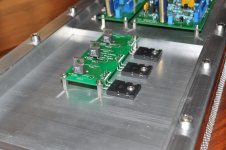
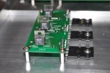
I have decided to finally finish off my KSA-50 Clone project and are planning to use the Caddock MP821 resistors as the emmiter resistors. Please see attached pics.
Is it OK if I mount them as shown? What size heatsink will I require for them for 5W use if they are rated for 20W? I am using the Pinkmouse boards.


Cheers
Henry
Is it OK if I mount them as shown? What size heatsink will I require for them for 5W use if they are rated for 20W? I am using the Pinkmouse boards.


Cheers
Henry
A typical value for the Case to Ambient thermal resistance of a TO220 device in free air is 61.5°C/W.
Reference source :
http://www.fairchildsemi.com/ds/FD/FDP3632.pdf
The MP821 has an additional thermal resistance of junction to case of 7.5°C/W.
So total resistance junction to ambient is 69°C/W.
The MP821 is rated at junction temperature of 175°C max.
That means you can run them in free air at approx. 2W with no margin.
Since you already have a heatsink for your power devices, the simplest solution is to use the same for the MP821.
i.e. mounting the MP821s on the bottom side of the PCB.
If you only want to use separate heatsinks for each MP821 to dissipate 5W, then I would recommend you use a heatsink of about 10°C/W or less.
You junction temperature would be then about 93°C above ambient.
Or use Fukushima MPC74 which is rated at 5W in free air.
Patrick
Last edited:
Patrick, thank you for your good scientific feedback. Since the resistors are already soldered in, I will be making a part from aluminium angle extrusion (38x38x6.3mm) and cut it so that I can connect the resistor thermally to the main heatsink. I assume that since you did not mention it that it is OK that I bent the legs like that and have them so close to the PCB. I was worried that the legs might get too hot and burn the PCB.
I future I will do my own PCBs for the outputs to cater for mounting the Caddocks in the same way that the output transistors are mounted, all be it on the other side of the PCB. I hope my Caddock experiment pays off. These resistors are expensive buggers.
I future I will do my own PCBs for the outputs to cater for mounting the Caddocks in the same way that the output transistors are mounted, all be it on the other side of the PCB. I hope my Caddock experiment pays off. These resistors are expensive buggers.
To question then is, how hot is too hot. Only the outcome of my experiment will answer that question. I might just have anough lead left to lift it slightly that there is a 1mm gap between the legs and the PCB. If that is still not enough then sleeving around the legs made of PTFE might be the answer. Else I will have to re-evaluate what I need to do.
- Status
- This old topic is closed. If you want to reopen this topic, contact a moderator using the "Report Post" button.
- Home
- Amplifiers
- Solid State
- Using a Caddock MP821 as an emitter resistor.