In designing a 3-way speaker its not uncommon to use a parallel LRC notch filter to flatten the woofer impedance. If this is not done, the crossover will interact with the woofer impedance to produce a strong woofer response anomaly. The value of R in the filter is roughly the desired impedance -- say 6 Ohms -- at resonance. Without the LRC filter, the impedance may rise to 40 Ohms or more at resonance. My question is, in terms of the amplifier current draw and power dissipation, are there any *disadvantages* to such a notch filter? The resistor in the LRC filter will in general have to dissipate alot of power, and that in itself is worrisome. So, since I am normally focused on the acoustic side, I thought I'd pose this question to those more in the know about the amplifier.
Last edited:
Hi Karl,Any help to him??
And how to flattening that "nominal" woofer/tweeter of 4-8 ohms to all the frequencies??
Its too bad the original question fell flat on its face. In a general sense, there are two aspects the question: (1) can the amplifier supply the required current at low voltages, (2) is the output impedance low enough so that a huge impedance swing does not alter the applied voltage. I am mostly concerned with (2).
To answer your question, one adds LRC notch filters to flatten out each impedance peak. However, this can be very costly in terms of parts so its not normally done. I guess the essence of the question is "is it worth it" to flatten the peaks.
Groeten,
Jeff
If you add extra components to the speaker to reduce the narrow bandwidth impedance peaks you are effectively pulling a lot more current from the amplifier.
This will make the amplifier run hotter and you will gain NO advantage in speaker performance.
If you have a passive crossover then that should already be designed to take account of the normal impedance variations that occur in drivers.
This will make the amplifier run hotter and you will gain NO advantage in speaker performance.
If you have a passive crossover then that should already be designed to take account of the normal impedance variations that occur in drivers.
Ok, let me see if I got it.
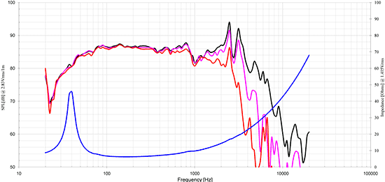
In the image below (the blue line), a given speaker (Peerless SLS830667 woofer, $66.00) has a "bump" of over 45 ohms around the 40Hz area. Then, around 80Hz it starts to be at the 10-8 ohms of "nominal" impedance up to nearly 1000Hz and then it rises again, right?
Now, what happen if trying to reproduce frequencies below the 80Hz?
I remember a DIYer here, way before placing the crossover in his project, putting first a resistor in parallel to "flatten" the speaker's impedance across the bandwidth. Can't find that thread/post anymore...
But would be VERY interesting to know how to do this, if one is looking for a good 8" woofer capable to deliver low ends without pushing the amp in those low frequencies...
@ jcandy
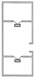
A parallel LRC notch filter can be helpful in flattening the impedance, of not just the Woofer, but Mids & Tweeters too. If all drivers are compensated in such a way, it's as below. But there's no free lunch, as the impedance/s are reduced downwards towards the DC resistance/s of each driver. But this makes it/them more sensitive by 3dB.
@ Karl vd Berg
The screenie of the Peerless SLS830667 is tested Unmounted in Free Air. In ANY box design the impedance peak will change, & in many designs there will be more than one peak.
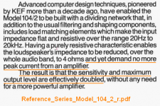
KEF pioneered smoothing out the impedance curve, across the Whole frequency response, in the 1980's. This is called Conjugate Load Matching
http://www.kef.com/uploads/files/en/museum_pdf/80s/Reference_Series_Model_104_2_r.pdf
A parallel LRC notch filter can be helpful in flattening the impedance, of not just the Woofer, but Mids & Tweeters too. If all drivers are compensated in such a way, it's as below. But there's no free lunch, as the impedance/s are reduced downwards towards the DC resistance/s of each driver. But this makes it/them more sensitive by 3dB.
@ Karl vd Berg
The screenie of the Peerless SLS830667 is tested Unmounted in Free Air. In ANY box design the impedance peak will change, & in many designs there will be more than one peak.
KEF pioneered smoothing out the impedance curve, across the Whole frequency response, in the 1980's. This is called Conjugate Load Matching
a crossover optimisation technique that presents a constant (albeit low) ohmic load to the amplifier https://en.wikipedia.org/wiki/KEF
http://www.kef.com/uploads/files/en/museum_pdf/80s/Reference_Series_Model_104_2_r.pdf
Your partially right, there is no free lunch............................... But there's no free lunch, as the impedance/s are reduced downwards towards the DC resistance/s of each driver. But this makes it/them more sensitive by 3dB...................
If the amplifier were able to deliver the same voltage into the parallel pair of the driver and the extra components , then the driver will reproduce exactly the same output. There is no extra 3dB.
BUT !!!!
the amplifier is now trying to drive a lower impedance and it must deliver more current and this is the "no free lunch". More heat and more stress.
@ Karl vd Berg
Yeah the RCF L8S800 is a nice driver, but with an fs of 60Hz, unless you tune the box lower you won't get down to 40Hz as you "appear" to want, & it won't be efficient down there either ! Have a look @ the 8" on here for more ideas US SPEAKER Home Page Menu - Speaker Cabinets, Guitar & amp; Bass Amps, upgrades and custom design. The world’s widest choice of speaker parts. “If you have listened to live music, you have almost certainly listened to Eminence” Anyway this is getting OT now, so it'd be better if you started a new thread in Multiway")
@ AndrewT
I recommend you take it up with KEF, as the info in the screenie is from their PDF i linked to earlier !
Here ya go - Contact KEF KEF
Yeah the RCF L8S800 is a nice driver, but with an fs of 60Hz, unless you tune the box lower you won't get down to 40Hz as you "appear" to want, & it won't be efficient down there either ! Have a look @ the 8" on here for more ideas US SPEAKER Home Page Menu - Speaker Cabinets, Guitar & amp; Bass Amps, upgrades and custom design. The world’s widest choice of speaker parts. “If you have listened to live music, you have almost certainly listened to Eminence” Anyway this is getting OT now, so it'd be better if you started a new thread in Multiway
@ AndrewT
I recommend you take it up with KEF, as the info in the screenie is from their PDF i linked to earlier !
Here ya go - Contact KEF KEF
Attachments
I suspect that the marketing dept, rather than the engineering dept wrote that
If you took a nominally 8 ohm driver and put an 8 ohm resistor in parallel with it The amplifier would see a nominally 4 ohm load. However the sound coming out of the speaker is not going to be magically doubled.
I think what you will find with the above copy is that the important piece of information is "and yet demand no more peak current from an amplifier"
This to me implies that they are actually increasing the impedance at points where it may dip below 4 ohms (when using nominally 4 ohm drivers). As when using 4 ohm drivers you may have some nasty dips to 2 ohms or lower which will cause stress to the amplifier.
So basically what I think that they are saying is that they have devised a way to use 4 ohm drivers without any nasty impedance dips.. In other words, it's marketing speak
Tony.
If that's the case, I can't see how it results in higher efficiency (ie I can't see it resulting in any additional SPL) It just means the amp will be working harder, and probably distorting more to achieve the same output levels...
Unless there is some magic involved
Tony.
Unless there is some magic involved
Tony.
KEF are a bit unusual in that some of their speaker models use a capacitor in series with the bass driver.
This raises the low frequency impedance and they claim it does not harm the bass extension in the way they have tuned their speakers.
Anything that parallels an impedance peak to help reduce that impedance peak will pull more current (same voltage and lower impedance = more current) from the amplifier and that equals more heat and more stress.
KEF are a bit unusual in that some of their speaker models use a capacitor in series with the bass driver.
This raises the low frequency impedance and they claim it does not harm the bass extension in the way they have tuned their speakers. ...
If done right it will actually improve bass extension. If I remember correctly Thiele & Small already described this. You can make a B3 or B5 alignment this way.
Depending on the amp, "heat and stress" may be essentially meaningless... and in the quest for ultimate sound quality, not an issue!
What probably makes a difference is what this sort of scheme does to the sound and overall sensitivity. Also, IF it can be used on ported speakers at all. In the case of ported speakers the impedance peaks are not merely a driver created effect, but a box/port effect. You can't stop the port from having a resonance, and that effecting the mechanical motion of the driver, in turn altering the impedance at the VC. I am not sure I have ever seen a paper on the acoustical effects of compensating the impedance peaks on both sides of a port resonance.
So, perhaps this compensation is limited to sealed boxes?
I suspect that this sort of compensation will alter the amplifier's electrical damping of the woofer, since some power will be in the network, not the VC, and anything in series with the woofer will certainly have the effect of a reduction in damping control when compared to a direct connection.
Better or worse? Probably depends on the specific implementation and speaker. For me KEF speakers always sounded nice, polite, but a bit "dead" overall. That appraisal is always subject to new input and change.
_-_-
@ wintermute
Because the speaker is 4R reduced from 8R, they can claim it's 3dB more sensitive than it otherwise would have been. Sure power is being consumed in the passive components, but the're designed to parterened with up to 200W into 4R Amps.
Interestingly they spec the sensitivity @ 2.83V which is "usually" for 8R. I expect it's to do with the Conjugate Loading.
KEF magic
Actually it isn't. Please see my screenie, also from KEF's PDF.
Yeah me too, but a Lot better than plenty of others
Because the speaker is 4R reduced from 8R, they can claim it's 3dB more sensitive than it otherwise would have been. Sure power is being consumed in the passive components, but the're designed to parterened with up to 200W into 4R Amps.
Interestingly they spec the sensitivity @ 2.83V which is "usually" for 8R. I expect it's to do with the Conjugate Loading.
KEF magic
Originally Posted by Bear
perhaps this compensation is limited to sealed boxes?
Actually it isn't. Please see my screenie, also from KEF's PDF.
For me KEF speakers always sounded nice, polite
Yeah me too, but a Lot better than plenty of others
Attachments
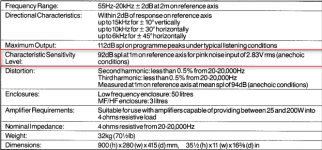
From that spec sheet, it appears the sensitivity is 92dB/2.83V @ 1m
Since the spec is for a 4ohms corrected impedance then the true sensitivity for 1W is 89dB/W @ 1m.
I suspect that had they left it as an 8ohms speaker with the correction to flatten the apparent impedance then they would have had a 92dB/W @ 1m speaker.
This seems to my understanding to be stating that the sensitivity has been reduced by applying the compensation. Not increased by 3dB.
That makes sense following from the other posts. Adding extra parallel components to reduce the impedance will draw extra current. That extra current is wasted energy and that equals reduced sensitivity.
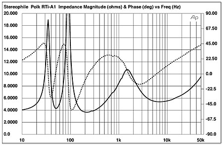
Phase Angles
in the impedance are what is causing amplifiers trouble.
When the current to the load is out of phase with the voltage the amplifier is seeing a virtual load that can be very demanding. Phase angles of +-45degrees are usually deemed acceptable, while phase angles as large as +-60 degrees can be damaging. The SOA of the output-transistors can be exceeded.
In the specific example the phase angle can be reduced significantly by simply adding a 40-60ohm resistor in parallel to the speaker. This will lower the total impedance, but not significanly so.
- Status
- This old topic is closed. If you want to reopen this topic, contact a moderator using the "Report Post" button.
- Home
- Amplifiers
- Solid State
- Advantages of flat LF speaker impedance for amps