
SUBZERO
Hello fellow forum would like to know if anyone har Zero sub amplifier, is an amplifier that caught my Atencio.
It is the famous Dr Jacoid
> Output power (RMS) 180W into 8 ohms -------------
> Output power (RMS) 230W into 4 ohms -------------
> Output (music) --------- 220-230W into 8 ohms
> Output (music) --------- 270-300W into 4 ohms
> Check osetljivost/impedansa----0, 6V/47koma (by 200Wrms ohms /
> ----- 7 Hz 112KHz-/-3dB frequency response (to less than 0.01% distortion)
> ------------------- THD <0.003% (a 130WRMS into 8 ohms)
> ------------------- THD <0.005% (a 180WRMS into 4 ohms)
> S/N------------ noise> 95 dB (compared to 100Wrms)
> ------- Damping factor> 300 (in 150WRMS into 8 ohms)
Notice of Copyright. Everything on this website is copyrighted by Dr. cheekbones Borivoje. Reproduction or re-publication by any means, electronic, mechanical or electro-mechanical, is strictly prohibited by international copyright laws. The author (Dr. Borivoje Jagodic) grants the reader the right to use this information for personal use and also allows one (1) copy may be made for reference. Commercial use is prohibited without the express written authorization of Dr. cheekbones Borivoje. Anyone interested in using my designs for the purposes commerrcial is free to contact me at my email address.
http://bas.elitesecurity.org/indexV.htmlEL DIAGRAM
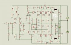
AMPLIFICADOR SUB ZERO
I'm making the diagram in proteus but I'm also good at it when I upload Temin archivo.Para help me simulate
AMPLIFICADOR SUB ZERO
I'm making the diagram in proteus but I'm also good at it when I upload Temin archivo.Para help me simulate
An externally hosted image should be here but it was not working when we last tested it.
http://rapidshare.com/files/1527875710/subzerosema.pdf
http://rapidshare.com/files/568906755/subzero.DSN

Last edited:
SUBZERO
Hello fellow forum would like to know if anyone har Zero sub amplifier, is an amplifier that caught my Atencio.
It is the famous Dr Jacoid
> Output power (RMS) 180W into 8 ohms -------------
> Output power (RMS) 230W into 4 ohms -------------
> Output (music) --------- 220-230W into 8 ohms
> Output (music) --------- 270-300W into 4 ohms
> Check osetljivost/impedansa----0, 6V/47koma (by 200Wrms ohms /
> ----- 7 Hz 112KHz-/-3dB frequency response (to less than 0.01% distortion)
> ------------------- THD <0.003% (a 130WRMS into 8 ohms)
> ------------------- THD <0.005% (a 180WRMS into 4 ohms)
> S/N------------ noise> 95 dB (compared to 100Wrms)
> ------- Damping factor> 300 (in 150WRMS into 8 ohms)
Notice of Copyright. Everything on this website is copyrighted by Dr. cheekbones Borivoje. Reproduction or re-publication by any means, electronic, mechanical or electro-mechanical, is strictly prohibited by international copyright laws. The author (Dr. Borivoje Jagodic) grants the reader the right to use this information for personal use and also allows one (1) copy may be made for reference. Commercial use is prohibited without the express written authorization of Dr. cheekbones Borivoje. Anyone interested in using my designs for the purposes commerrcial is free to contact me at my email address.
http://bas.elitesecurity.org/indexV.htmlEL DIAGRAM
AMPLIFICADOR SUB ZERO
I'm making the diagram in proteus but I'm also good at it when I upload Temin archivo.Para help me simulate
AMPLIFICADOR SUB ZERO
I'm making the diagram in proteus but I'm also good at it when I upload Temin archivo.Para help me simulate
An externally hosted image should be here but it was not working when we last tested it.
http://rapidshare.com/files/1527875710/subzerosema.pdf
http://rapidshare.com/files/568906755/subzero.DSN
upload info
Attachments
Last edited:
please share also the PCB foil pattern and lay-out
Just make the diagram.
in proteus software.
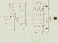
Now I want to make the simulation of the amplifier.
No simulation runs.
So I turned up the diagram.
to check for errors.
I would like to help me check.
Best regards sergio.
Just saw this thread and thought I could help, sorry its late.
I've had to make some very minor changes.
Hope its what you wanted.
I use Proteus for PCB design and microcontroller sim,
but I find it limiting, something like Multisim is more versatile.
Regards
Edit: fuses are shorted out to simulate graphs, since they don't have proper sim data.
I've had to make some very minor changes.
Hope its what you wanted.
I use Proteus for PCB design and microcontroller sim,
but I find it limiting, something like Multisim is more versatile.
Regards
Edit: fuses are shorted out to simulate graphs, since they don't have proper sim data.
Attachments
Last edited:
What's the interest? - this design is 95% Hitachi app. notes from >30 years ago.
It only differs in minor details and by using modern LATFETs. Get rid of the sluggish
MJE340/350 and use decent VAS transistors and watch it improve. You will find it
has been simmed by a lot of folks who only just rediscovered it for themselves.
It only differs in minor details and by using modern LATFETs. Get rid of the sluggish
MJE340/350 and use decent VAS transistors and watch it improve. You will find it
has been simmed by a lot of folks who only just rediscovered it for themselves.
Last edited:
idk, but I just corrected some things, so he can see how to get a circuit to sim in Proteus,
Now he can change things, to any topology.
Maybe IPS and VAS from Apex SR200 with some mosfets at output,
Its similar IPS and Diff VAS structure, just pimped to the max
Regards
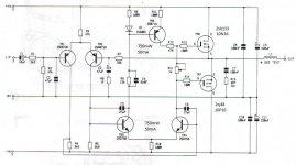
Attached: Just for reference sake, heres a old Mosfet Amp.
Now he can change things, to any topology.
Maybe IPS and VAS from Apex SR200 with some mosfets at output,
Its similar IPS and Diff VAS structure, just pimped to the max
Regards
Attached: Just for reference sake, heres a old Mosfet Amp.
Attachments
Last edited:
You need to have the same Vce on Qs 5&6, and to a lessor degree Qs 7&8. I would change the mirror (Qs 7&8) to a Wilson mirror. This way you can use better matched small signal transistors for the mirror and only need 1) TO-126 device to load the VAS. As for Qs 5&6, you need to add a cascode to Q5, where Q5 collector drives emitter of BJT (or source of fet), base (gate) tied to GND, and collector (drain) connected to the mirror. This will make it so as the average Vce of Qs 5&6 are equal, so then is Pd and temperature rise. Since Vbe is dependent on temperature, if one LTP device gets hotter than the other it will throw off the balance and you want to maintain a balance in the LTP in order to maintain stable DC bias and have a more symetrical transfer function.
very well
Thanks looks luxurious VOSTRO I also do not use the Multisim well, so I wanted to help. In your opinion after such a simulation is how much power this amp came with an eight-ohm load.
the bias of each transistor is 120 + milliamps
PS I did the PCB in proteus for I see that I think there is easier to make the pcb in ares

Just saw this thread and thought I could help, sorry its late.
I've had to make some very minor changes.
Hope its what you wanted.
I use Proteus for PCB design and microcontroller sim,
but I find it limiting, something like Multisim is more versatile.
Regards
Edit: fuses are shorted out to simulate graphs, since they don't have proper sim data.
Thanks looks luxurious VOSTRO I also do not use the Multisim well, so I wanted to help. In your opinion after such a simulation is how much power this amp came with an eight-ohm load.
the bias of each transistor is 120 + milliamps
PS I did the PCB in proteus for I see that I think there is easier to make the pcb in ares
- Status
- This old topic is closed. If you want to reopen this topic, contact a moderator using the "Report Post" button.
- Home
- Amplifiers
- Solid State
- Amplificador SUBZERO