Hi guys, one of my first posts here.... I'm a telecom technoligist playing in vintage audio stuff for a few years now I've learned quite a lot on amps in those few years but way less then you guys.
I'm rebuilding a nice Son of Ampzilla. Up to now I've replaced all lytics with Panasonic FM and 2 big ELNA 10k uF 63 volts.
When IVe received and first powered this amp, one side had very low power, even seems only high's going through... After I did re-hooked the amp to speakers and pre, both channels were good? What the hell, let's use it!
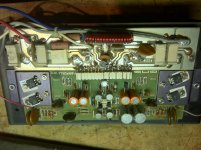
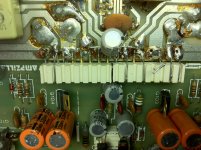
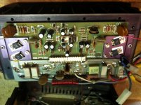
Brought it home and here again, the right channel was weak. Let's open the machine... Found a few strange things; it's beed fixed before. On the left channel (the one that works), the connector strip between the 2 cards was jumped: some wires were soldered over the connector and back to the card except pin 3 that was left open? Thought that was a "mistake" so soldered it again. Powered it up and it got red hot after a minute or 2...? Didn't have time to see if audio was coming out. So removed that link, verified drivers & outputs, and left channel is back working normally(?). I'll post some pictures of this.
And, while playing with capacitors on the power card, I could hear the right channel going up and down so I suspect some bad soldering under this card.
So I did removed all cards, verified all semi's (diodes, transitors) and they were all good. They were all GAS still. No ones have been replaced.
Here I am now; A fully recapped SOA ready to be back to original config. So I'ld like to adjust all the pots correctly. Even, while I'm there, I could replace some resistors, diodes, caps, that you, knowledged guys, would do if you'ld be here. I have in my stuff some MJ21193/21194, MJ15030, 15031, HS4007, etc.
SO... Can someone guide me through the alignment of this beauty? I guess I'll come into problem with this "pin 3" link that is at 45 VDC (or around... I'm getting old).
All I cound find on the net is that "marked" schematics. Would anyone be nice enough to get me some decent schematics, or even a service manual with pin-outs, etc? I know now how to adjust 0V on speakers and set bias @ 30mv on the output emitter resistors but the other pots are magic to me.
Thanks
I'm rebuilding a nice Son of Ampzilla. Up to now I've replaced all lytics with Panasonic FM and 2 big ELNA 10k uF 63 volts.
When IVe received and first powered this amp, one side had very low power, even seems only high's going through... After I did re-hooked the amp to speakers and pre, both channels were good? What the hell, let's use it!
Brought it home and here again, the right channel was weak. Let's open the machine... Found a few strange things; it's beed fixed before. On the left channel (the one that works), the connector strip between the 2 cards was jumped: some wires were soldered over the connector and back to the card except pin 3 that was left open? Thought that was a "mistake" so soldered it again. Powered it up and it got red hot after a minute or 2...? Didn't have time to see if audio was coming out. So removed that link, verified drivers & outputs, and left channel is back working normally(?). I'll post some pictures of this.
And, while playing with capacitors on the power card, I could hear the right channel going up and down so I suspect some bad soldering under this card.
So I did removed all cards, verified all semi's (diodes, transitors) and they were all good. They were all GAS still. No ones have been replaced.
Here I am now; A fully recapped SOA ready to be back to original config. So I'ld like to adjust all the pots correctly. Even, while I'm there, I could replace some resistors, diodes, caps, that you, knowledged guys, would do if you'ld be here. I have in my stuff some MJ21193/21194, MJ15030, 15031, HS4007, etc.
SO... Can someone guide me through the alignment of this beauty? I guess I'll come into problem with this "pin 3" link that is at 45 VDC (or around... I'm getting old).
All I cound find on the net is that "marked" schematics. Would anyone be nice enough to get me some decent schematics, or even a service manual with pin-outs, etc? I know now how to adjust 0V on speakers and set bias @ 30mv on the output emitter resistors but the other pots are magic to me.
Thanks
Attachments
TRy this link for download in PDF.
I do not know how good it is:
Categorized Schematics and Service Manuals for free download
It is from this site which have plenty of download: Audio Circuit Denmark
I do not know how good it is:
Categorized Schematics and Service Manuals for free download
It is from this site which have plenty of download: Audio Circuit Denmark
I'm rebuilding a nice Son of Ampzilla. Up to now I've replaced all lytics with Panasonic FM and 2 big ELNA 10k uF 63 volts.
When IVe received and first powered this amp, one side had very low power, even seems only high's going through... After I did re-hooked the amp to speakers and pre, both channels were good? What the hell, let's use it!
Here I am now; A fully recapped SOA ready to be back to original config. So I'ld like to adjust all the pots correctly. Even, while I'm there, I could replace some resistors, diodes, caps, that you, knowledged guys, would do if you'ld be here. I have in my stuff some MJ21193/21194, MJ15030, 15031, HS4007, etc.
SO... Can someone guide me through the alignment of this beauty? I guess I'll come into problem with this "pin 3" link that is at 45 VDC (or around... I'm getting old).
Thanks
Hi,
The Son is a great amp! Even after 35 years there are still a lot of them out there making music, the sign of a true classic. I hope you enjoy it.
It wasn't clear from your post whether the problem with the channel was fixed by the cap upgrade and other work you applied or if it's still intermittant. If it is still a problem there are two common issues I see with this version of the drive card.
The most common is intermittant input differential transistors (or the connections to the transistors in the socket). A new set of transistors is always warranted at this age. They need to be matched but luckily the devices are inexpensive. I use low noise Toshiba devices but the original Motorola numbers are still available and normally have a pretty tight distribution, even in small quantities, so matching them is not a big hurdle.
The second common issue, which can act like an intermittant is the Fairchild TO220 devices used as both the voltage amps and the drivers. I change these out whenever I see them as they are a headache waiting to happen. Good numbers to use are 2SD613/2SB633. Both availible from BD enterprises (BDent.com). These original devices did not age well and will cause a variety of symptoms, with intermittant being high on the list.
As for setup you already have the basics as you described. The other two controls set the point where the limiters kick in and to be honest you are better off disabling the limiters as it is an ancient approach that, while well designed, does not really bring anything to the amps performance. In my younger "bat ears" days I could easily hear a subtle improvement when they were removed from the signal path. For the most part you will have to really be pushing the amp to get them to respond at all.
Enjoy,
Mike
Thanks a lot Mike, I'll sure will replace all those TRs. Should I also replace the OPs by MJ21194/93? I have bunch of them available. I even have some pairs of faster ones (25MHZ) 2SA747, 2SC1116 (original SANKENs).
And for the TO220, I have some MJE15030/31 availables. Would they be good you think?
Oups, just forgot to write that when I brought the amp home, the right channel got back to it's faulty state for goods. I've noticed that playing arounf the 2200uf caps on the PS board the level seemed to rise and lowered. I may have a problem of a bad contact under the P.S. board. I'm there to refurbish now, both side boards have been done, only the PS left to do. I'll sure will redo all the soldering at the connections. Should I use silver solder? Is it "harder" then regular solder?
And for disabling the limiters, how Do I do it? Just set the pot at one end? Remove the pots?
Thanks again Mike!
Last edited:
Hi,
nice that I found this thread, as I am rebuilding a SOA now. I boght it the other day with distortion in one channel, I got home and it is humming from both channels. I will also use Panasonic caps, but I'm thinking on using the FR's, specs are the same as the FM, but they last longer. I was advised to increase the capacity of the power supply caps and to use higher voltage specification all arround.
I didnt know about the input transistors, but since I am there, will replace them also.
I am curious about how to disasble the protection circuits. What is the procedure to do this? Just remove the components? By pass it?
I will also move the 4A fuse to a new holder inside the amp's box and use the hole in the back panel to install a on-off switch.
Ricardo
I was looking at the schematics for a way to disable the limiters, is it enough just to remove the transistors Q103 and Q104? Or do we have to remove the 4 resistors (R123, 124, 105, 106) the diodes D101 and 108 and the variable resistors?
Ricardo
I remove the transistors and leave the rest. As for the replacing the output transistors, if it still has the original Toshiba 2SD424/2SB554s I use them as they are good and GAS matched them well. A quick check of the voltage drop across the .2 ohm emitter resistors to verify if the bias between the transistors is close (<5mv between all) this is a good gauge of whether or not to change them. The high speed transistors might need a different compensation cap on the voltage amp transistors if there is any tendency to oscillate. The current cap is 20 pf and I have had to go up to 100pf with the motorolas devices ElectroChap mentioned.
The hum can happen if the main ground screw to the power supply PCB/chassis is loose, or if someone has upgraded to new input connectors and used insulators for the jacks. The original design grounded the driver card through the connection of the jacks to the chassis. I see this problem fairly regularly.
Regards,
Mike
And for the TO220, I have some MJE15030/31 availables. Would they be good you think?
only the PS left to do. I'll sure will redo all the soldering at the connections. Should I use silver solder? Is it "harder" then regular solder?
Thanks again Mike!
Hi,
The MJ15030/31 should be fine. I have used the Japanese parts for years so I haven't compared the specs on the Motorolas in a long time so you might double check. As for silver solder, it can't hurt but I have heard this amp sound really good with Kester
")
Regards,
Mike
I remove the transistors and leave the rest. As for the replacing the output transistors, if it still has the original Toshiba 2SD424/2SB554s I use them as they are good and GAS matched them well. A quick check of the voltage drop across the .2 ohm emitter resistors to verify if the bias between the transistors is close (<5mv between all) this is a good gauge of whether or not to change them. The high speed transistors might need a different compensation cap on the voltage amp transistors if there is any tendency to oscillate. The current cap is 20 pf and I have had to go up to 100pf with the motorolas devices ElectroChap mentioned.
The hum can happen if the main ground screw to the power supply PCB/chassis is loose, or if someone has upgraded to new input connectors and used insulators for the jacks. The original design grounded the driver card through the connection of the jacks to the chassis. I see this problem fairly regularly.
Regards,
Mike
Thanks Mike,
I will leave the output transistors alone if everything measures fine.
The input conectors are the original ones, if I decide to replace them, I will not insulate.
Cant wait for the new caps to arrive to finish the job and to plug it to my Infinitys
Regards
Ricardo
I have one of these on my bench right now. I need to find schematics!
This schematics are the best ones I found... Not perfect, buit big enough to guess the components values.
Ricardo
An externally hosted image should be here but it was not working when we last tested it.
I bought one two weeks ago and haven't opened it yet, but upon getting it home I was disappointed in the bass, so will be working on it over the next few months. Glad to see others blazing a trail.
The supply flters and all the electrolytics are 35 years old. Also pull the 330uf bypassing the 150 ohm emitter resistors in the input stage... Also make sure the screw for the bridge rectifier is tight as this provides the chassis ground and reference for the input stages.
Bass is not a problem with this amp, unless you like it fat, slow
Regards,
Mike
The original design didn't use a grounded chassis; the transformer design reflects this. I don't use the ground when I install an IEC plus on this model. I stick with the original design because when I have added the ground, it created grounding issues in the owners' systems that weren't there previously. Therefore, I'm faithful to the original design. If it's grounded, like the Ampzilla is, then I do use it.
Hi all,
I finished the replacement of the caps, installed a nice power switch, moved the fuse inside the enclosure, calibrated the VU meters with a function generator and powered the SOA on... One channel is perfect, almost 0V DC on the outputs, the bias is a nice 30mV on all the resistors, everything fine. On the other channel, Ov DC on the outputs, but when placing the probes across any of the 4 resistors I have nothing, 0V! The supply is ok and I cant find any obvious fault in the circuit. Am I missing something obvious? Should I statart looking for new output transistors? The bias IC? This thing scares me a bit, since its impossible to find one...
Tomorrow I will test all transistors individually, but any ideas are very welcome.
Thanks
Ricardo
My SOA is fixed and sounding great!
For those you need to replace the output transistors, please note that the GAS transistor cross reference has a small mistake.
The GAS118 is the NPN and the GAS119 is the PNP, use the schematics as a reference.
I ended up using MJ15022 and MJ15023 on the outputs with nice results.
Ricardo
For those you need to replace the output transistors, please note that the GAS transistor cross reference has a small mistake.
The GAS118 is the NPN and the GAS119 is the PNP, use the schematics as a reference.
I ended up using MJ15022 and MJ15023 on the outputs with nice results.
Ricardo

- Status
- This old topic is closed. If you want to reopen this topic, contact a moderator using the "Report Post" button.
- Home
- Amplifiers
- Solid State
- Son of Ampzilla rebuilt