
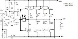
250W/4R with a +/-40V power supply?
Have you tested this or just estimated it from theoretical maximum figures?
Hello . Not personally tested. I have designed the pcb for my friend MadMax. This project belongs him.
You can see it at 250-400W Power Amplifier | Electronic City
typical Beginners' mistake. And as Beginners they are excused, this is a learning Forum.250W/4R with a +/-40V power supply?
Have you tested this or just estimated it from theoretical maximum figures?
It's the "NOT Beginners" that promulgate this type of useless information and are simply lies, that get up my nose.
Now back to the learning for Beginners.
250W into 4ohms is equivalent to 44.7Vpk and 11.2Apk delivered simultaneously to the 4r0 load.
Expect the supply rails for the 250W amplifier to be about +-55Vdc, not +-40Vdc.
A 37Vac+37Vac to 40Vac+40Vac transformer of about 400VA to achieve target performance. If you want two channels then two transformers or double the VA requirement.
Yet another unhelpful post?
Last edited:
undsperdicio diseñño then this is of no use. A much power really comes. : Confused:typical Beginners' mistake. And as Beginners they are excused, this is a learning Forum.
It's the "NOT Beginners" that promulgate this type of useless information and are simply lies, that get up my nose.
Now back to the learning for Beginners.
250W into 4ohms is equivalent to 44.7Vpk and 11.2Apk delivered simultaneously to the 4r0 load.
Expect the supply rails for the 250W amplifier to be about +-55Vdc, not +-40Vdc.
A 37Vac+37Vac to 40Vac+40Vac transformer of about 400VA to achieve target performance. If you want two channels then two transformers or double the VA requirement.
Yet another unhelpful post?
I'd say around 90W into 8 ohms. The number of output transistors added is irrelevant. It is the maximum output voltage swing that defines the output power. The number of output transistor pairs simply allows handling of the required current.
The circuit will also perform poorly. There is no bias on the additional output transistors, so they will operate in class B and cause distortion. There is also no drive stage for these transistors so the amplifier IC will spend a good deal of its max output current driving this stage, further increasing distortion.
There is no such thing as an "easy"/"cheap" powerful amplifier.
Well, that's somewhat true when we use serious amplifiers at pro. entertainment levels but with newb home audio and imaginary power that won't often be used above low levels, they won't sustain medium to high levels for long at all. Speakers to handle the high power are going to be more expensive than the amplifier.......You tend to hear crossover distortion at lower levels.
At medium to higher power outputs you wont notice it.
They'll typically just sit in the garage or bedroom playing into domestic speakers and sounding like fingernails on a chalkboard.

The 'music power' rating of the TDA is 100W at 10% distortion, 70W at 0.5% distortion.
The extra outputs will allow it to drive a lower impedance, so you might get 150W/4Ω with a stiff ±40V supply.
An 8Ω resistor should be hooked from the output of the TDA to the speaker out.
The extra outputs will allow it to drive a lower impedance, so you might get 150W/4Ω with a stiff ±40V supply.
An 8Ω resistor should be hooked from the output of the TDA to the speaker out.
I am going to say that is an over estimate.I'd say around 90W into 8 ohms..........
If the supply droops by 3V and the losses through the amplifier account for a further 3V then the maximum peak voltage into the load is 40-[3*2] = 34Vpk.
The maximum output power would be 34^2/16 = 72W into 8r0.
If the two losses are 4v each, then max Power would be 64W into 8r0.
If the two losses are 5v each, then max Power would be 56W into 8r0.
These are the kind of assessments that readers of data should be doing, rather than accepting wild claims that cannot possibly be anything other than downright lies.
"Back of a fag packet" assessments do not need to be accurate, they are fast and every Member who is interested in building amplifiers should be capable of learning how to do this. It is DIY after all.
Last edited:
BRIDGE
comvencioanl best to use the TDA7294 in bridge mode. It's much better.
I am going to say that is an over estimate.
If the supply droops by 3V and the losses through the amplifier account for a further 3V then the maximum peak voltage into the load is 40-[3*2] = 34Vpk.
The maximum output power would be 34^2/16 = 72W into 8r0.
If the two losses are 4v each, then max Power would be 64W into 8r0.
If the two losses are 5v each, then max Power would be 56W into 8r0.
These are the kind of assessments that readers of data should be doing, rather than accepting wild claims that cannot possibly be anything other than downright lies.
"Back of a fag packet" assessments do not need to be accurate, they are fast and every Member who is interested in building amplifiers should be capable of learning how to do this. It is DIY after all.
comvencioanl best to use the TDA7294 in bridge mode. It's much better.
Attachments
Last edited:
its a simple fact that both of the original circuits are rubbish from any possible aspect IE sound quality , stability, and rated power .
The only interesting here is to try to understand why ( this should be the benefit of this thread and only )
In theory and given as a fact low losses and perfect power supply the circuit might work and even might produce original specs taking also as a fact that we talk about classic tests which is 1KHZ sine wave at resistive load .
In a speaker inductive load security/safety mechanisms inside the tda will not allow the same performance
By the same logic the resistor of 8 ohms from TDA to actual load might lift the TDA away from the problems and increase performance by a bit .
Also let us not forget that he basis of all these circuits is the original application of the TDA 2030 but on a single rail and coupled with a capacitor in the output of course...
Now for those who don't remember the specific geriatric circuit featured lower distortion eventhough not so much power , extremely musical , and very tolerant to weird/low loads long cables and so on and on ....
Kind regards
sakis
Having no bias isn't the end of the world.
You tend to hear crossover distortion at lower levels.
At medium to higher power outputs you wont notice it.
yes...and for PA duties no big deal really....
T
An 8Ω resistor should be hooked from the output of the TDA to the speaker out.
That s the solution to keep on working on AB class at low power
but the actual most efficient value is about 1R.
Attachments
To make a long story short:
1) dear sergiods: don't build that amp.
2) Yes, *maybe* the designer tried to extrapolate the old "boosted TDA2030", why not?
But he missed biasing and a couple extra details.
Of more importance is that the TDA7294 is not a good choice here.
a) it does not swing close to the rails , wasting necessary voltage (while a discrete drive stage or a dedicated driver chip is meant to do that) and
b) its power dissipation and current capability is wasted .
Plus its inherent rail voltage limit is way below what the the output transistors can handle.
To drive power transistors run from +/- 40V, you really don't need much more than what a couple TIP31/32C can offer.
But, hey!!, we all began one way or another !!!
- Status
- This old topic is closed. If you want to reopen this topic, contact a moderator using the "Report Post" button.
- Home
- Amplifiers
- Solid State
- 250-400watt audio amplifier